III
Up_per
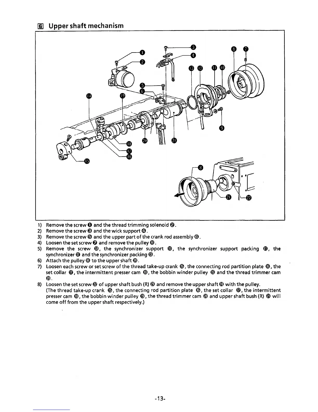
shaft mechanism
1}
Remove
the screw 0 and the thread trimming solenoid@.
2)
Remove
the
screw@)
and the wick support
0.
3)
Remove
the screw 0 and the upper part
of
the crank rod assembly@.
4)
Loosen
the set screw G and remove the pulley@.
5)
Remove
the screw
@)
1
the
synchronizer support ®
1
the synchronizer support packing
tD
1
the
synchronizer@ and
the
synchronizer packing@.
6)
Attach the pulley@
to
the
upper shaft
ID.
7)
Loosen
each
screw or set screw
of
the thread take-up crank
@,the
connecting rod partition plate
(@
1
the
set collar
0
1
the
intermittent
presser
cam
4ID
I
the
bobbin
winder
pulley @
and
the thread trimmer
cam
w.
8)
Loosen
the set screw 0
of
upper shaft
bush
(R)
fD
and remove the upper shaft
ID
with
the
pulley.
(The thread take-up crank
@,the
connecting rod partition plate (@,the
set
collar 0 I
the
intermittent
presser
cam
4ID,
the bobbin winder pulley
@I
the
thread trimmer
cam
W and upper shaft
bush
(R)
fD
will
come
off
from the upper shaft respectively.)
-13-