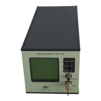
Measuring Ampifier Type 2525
User Manual Vol.1
4–7
BE1406–12
Chapter 4 –The Menus
Main Set-up
FLOATING* Values appear on the screen in Scientific Notation
(floating point). For example, 10E-02.
ATTENUATOR DEPENDENT Values appear as real numbers (fixed point) with the
decimal position determined by the attenuator set-up.
4.2.9 Mounted Resonance
*
This is a two-stage menu. First select an impulse frequency for the mounted accel-
erometer. This is done using the Up/Down arrow pushkeys. Then select Measure
Resonance to read out the measured mounted resonance frequency for the acceler-
ometer:
SELECT IMPULSE FREQUENCY Opens the Impulse Frequency Setting menu
MEASURE RESONANCE Measurement of the mounted resonance frequen-
cy of the transducer starts. The range of values
returned is from 3 to 60kHz. The resolution in
range 3 to 10kHz is 10Hz and in 10 to 60kHz is
100Hz.
Note: This function can be used with a large number of Brüel&Kjær Charge Accel-
erometers, but not all. Contact your Brüel&Kjær representative to make determine
which accelerometers can be used.
Impulse Frequency Setting Menu
When you choose SELECT IMPULSE FREQUENCY in the Mounted Resonance menu, this
menu will appear allowing you to enter a value for the impulse frequency. The
range is from 3.0 to 60.0kHz with a resolution of 10Hz from 3 to 10kHz and
100Hz from 10 to 60kHz. The default value is 30kHz. As a starting point, we
recommend that you use the mounted resonance frequency as stated on the scceler-
ometer’s calibration chart or in its Product Data (specifications).
4.2.10 Display Mode
This menu allows you to specify the format for the measurement read-out.:
DIGITS + BAR-GRAPH* The display appears as shown in Fig.4.1.
The Digits + Bargraph option allows you to view the measurement as it takes place
in terms of a bar graph as well as showing each current level.
LARGE DIGITS The display appears as shown in Fig.4.2.
*Patent pending

 Loading...