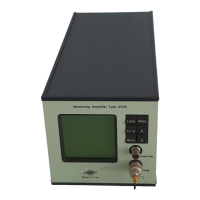
Measuring Ampifier Type 2525
User Manual Vol.1
Brüel & Kjær
6–6
Chapter 6 –Making a Measurement
Instructions for Measurement
Note: Normally the Input gain is set first and IF an overload occurs, you can
reduce the Input Gain, and increase the Output Gain until you have the gain
you require. For this example, then, any adjustment of the Output Gain to
achieve an overload is purely for the purpose of demonstration.
2. Make a note of the value at the AC output which appears at the bottom of the
measurement mode screen.
3. Return Input Gain to 30dB, and Output Gain to 0dB.
The type of overload is indicated at the bottom of the amplifier’s screen with DC
overloads given the highest priority. If you have both a DET OVL as well as a CM
OVL, the screen will toggle between the two messages. If you have both an AC
overload and are also using the Reference Generator option, the messages SIG OVL
and REF GEN will also toggle on the screen.
Note that, even while an overload message appears on the screen, the amplifier
continues to measure. This means that, unless you re-adjust your gain values and
start the measurement again, the data you are recording will be influenced by the
overload conditions.
6.4.3 Alarm Settings
Besides monitoring your data for overloads, you may have a particular reason for
monitoring how often, or how long levels exceed a given value. The Alarm Function
allows you to specify this value and how long the value may be exceeded before it is
“captured” or held by the amplifier for a specified duration.
This is a useful function in production line monitoring situations. If it is, for exam-
ple, acceptable that the level exceeds a particular limit once every five minutes you
can check this by observing how many times in the course of five minutes the
Alarm message appears on the screen.
To set the Alarm Function from the measurement mode (Digits + Select) screen:
1. Make a note the RMS value shown in the Digits + Select Screen.
2. Move the cursor to “To main setup” and press .
3. Select Measurement Setup, and then Alarm Function.
4. Move the cursor to the following and select:
● Alarm On/Off = On
● Alarm Detector = RMS
● Alarm Level = Select a value which comes very close to the measured RMS
value you noted in (4), but is just a little higher
● Alarm (Level) Hold Time = 1s
Setup

 Loading...