93
ZTKS0164 / Z31949 / 06
List of Figures
A.2 Figures
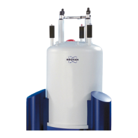
Figure 1.1: General view of a magnet system with 2 helium turrets ...................... 10
Figure 2.1: Safety devices of the cryostat with 2 helium turrets............................. 25
Figure 3.1: Packaging (without surrounding panels).............................................. 29
Figure 3.2: Transportation by fork lift – front view .................................................. 31
Figure 3.3: Transportation by fork lift – rear view................................................... 31
Figure 3.4: Attachment points for lifting equipment................................................ 32
Figure 3.5: Instruction label for lifting equipment ................................................... 32
Figure 5.1: Start the magnet stand......................................................................... 38
Figure 5.2: Stop the magnet stand......................................................................... 38
Figure 6.1: Magnet system during a quench.......................................................... 54
Figure 9.1: Dimensions of the cryostat (front view)................................................ 61
Figure 9.2: Dimensions of the cryostat (top view) .................................................. 63
Figure 9.3: Safety valves of the cryostat ................................................................ 64
Figure 9.4: Nitrogen level sensor ........................................................................... 65
Figure 9.5: Helium level sensor.............................................................................. 66
Figure 9.6: Characteristic curve of PT 100 sensor................................................. 67
Figure 9.7: Characteristic curve of IBT carbon sensor........................................... 68
Figure 9.8: Fringe field plot of the magnet system at maximum field..................... 70
Figure 9.9: Nitrogen level graph............................................................................. 72
Figure 9.10: Helium level graph ............................................................................... 73
Figure 9.11: Magnetic center and shimsystem offset (SO) ...................................... 77
Figure 9.12: High current lead 55 pin....................................................................... 81
Figure 9.13: Wiring diagram magnet........................................................................ 82
Figure 9.14: Wiring diagram magnet control and shims........................................... 83
Figure 9.15: Wiring diagram magnet diagnostic and temperature sensors.............. 84
Figure 9.16: Shorting plug 55 pins .......................................................................... 85

 Loading...