Graphics Display
SMART MATRIX FEEDER 2-45
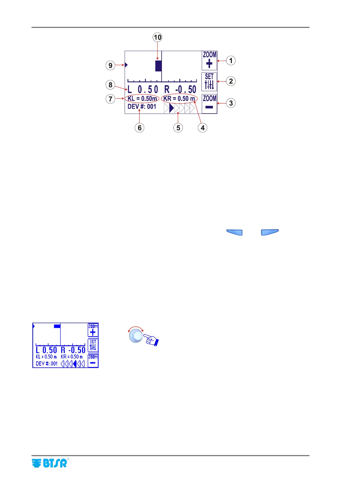
1) ZOOM + button (with respect to the horizontal scale)
2) Option setting button (flat/measure and carriage direction determination mode)
3) ZOOM – button (with respect to the horizontal scale)
4) KR constant (*)
5) Carriage movement direction (in the above example: from left to right); in the opposite direction the
arrows are reversed
6) Device currently selected by means of rotary selector (it is graphically indicated by the arrow 9)
7) KL constant (*)
8) LFA values of the currently selected device, in both directions (L – left and R – right)
9) Symbol that indicates the position where the ULTRAFEEDER/ROLLING FEEDER/UNIFEEDER
device in installed. Such position may be changed manually using the
and buttons.
The example shown on the picture above indicates that the ULTRAFEEDER/ROLLING
FEEDER/UNIFEEDER device is installed to the left.
10) Graphic bar indicating the shift in one of the two directions with respect to the optimum condition
(*) K is a constant value added in one direction and subtracted in the other direction. This is due to the
fact that in one of the two directions, besides the yarn used for the actual manufacturing process, an
extra amount of yarn is consumed, as the carriage moves away from the position where the
ULTRAFEEDER/ROLLING FEEDER/UNIFEEDER device is mounted; in the other direction, i.e. during
the carriage approach movement, the machine uses the amount of yarn already drawn in the previous
movement.
Setting the KL and KR values.
Click on the rotary selector to select KL or KR setting
field (according to the installation position of
ULTRAFEEDER/ROLLING FEEDER/UNIFEEDER
device).