Installation6
Logamax plus GB162-80 kW/100 kW - Subject to modifications resulting from technical improvements!26
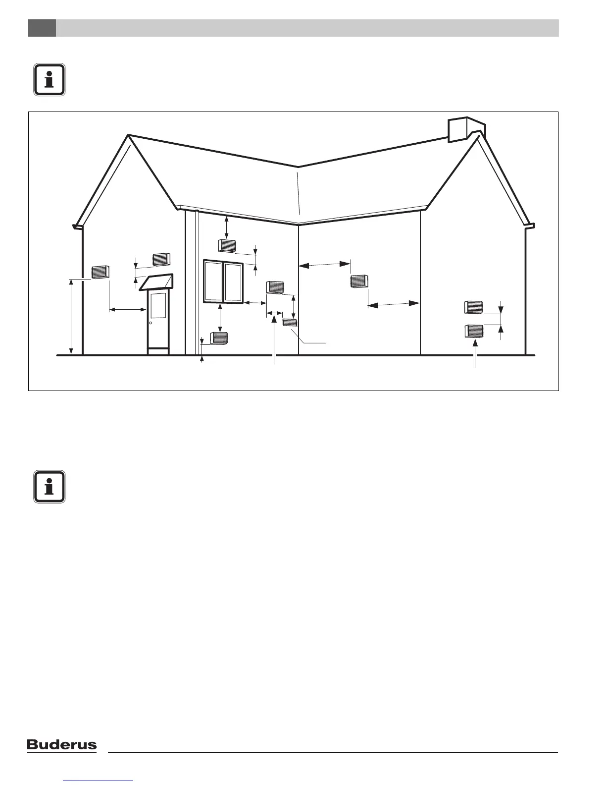
Below are approved examples of vertical and horizontal
venting installation
NOTICE
A minimum clearance of 4 ft (1,220 mm) horizontally from and in no case above and below, unless a 4-foot
(1,220 mm) horizontal distance is maintained, from electric meters, gas meters, regulators and relief equipment
Fig. 22 Vent and air pipe position (2) of a system with combustion air supply from the room (non-room sealed)
1'
3'
3'
1'
4'
4'
7'
4'
1'
3'
5'
(2135 mm)
(305 mm)
(1220 mm)
(1525 mm)
(1220 mm)
(915 mm)
(915 mm)
(305 mm)
(305 mm)
(1220 mm)
(1220 mm)
Gravity Air Inlet
Exhaust terminal must be at least 3 ft (915 mm)
above forced air inlet within 10 ft (3,050 mm)
at least 1 ft (305 mm)
above grade and snow line
Forced
Air Inlet
NOTICE
z Place pipe supports every 5 feet (1,525 mm)
of horizontal and vertical run, beginning with
support near boiler.
z The condensate must be drained in accor-
dance with the applicable rules.
See paragraph 6.4: "Connecting the
condensate drain pipe" on page 21.
z Periodic cleaning of the vent terminal and
air-intake screens is mandatory.
z Avoid locating vent terminals near equip-
ment or construction which can be subject to
degradation from exhaust gases.