1-42 2007 Buell Firebolt: Maintenance
HOME
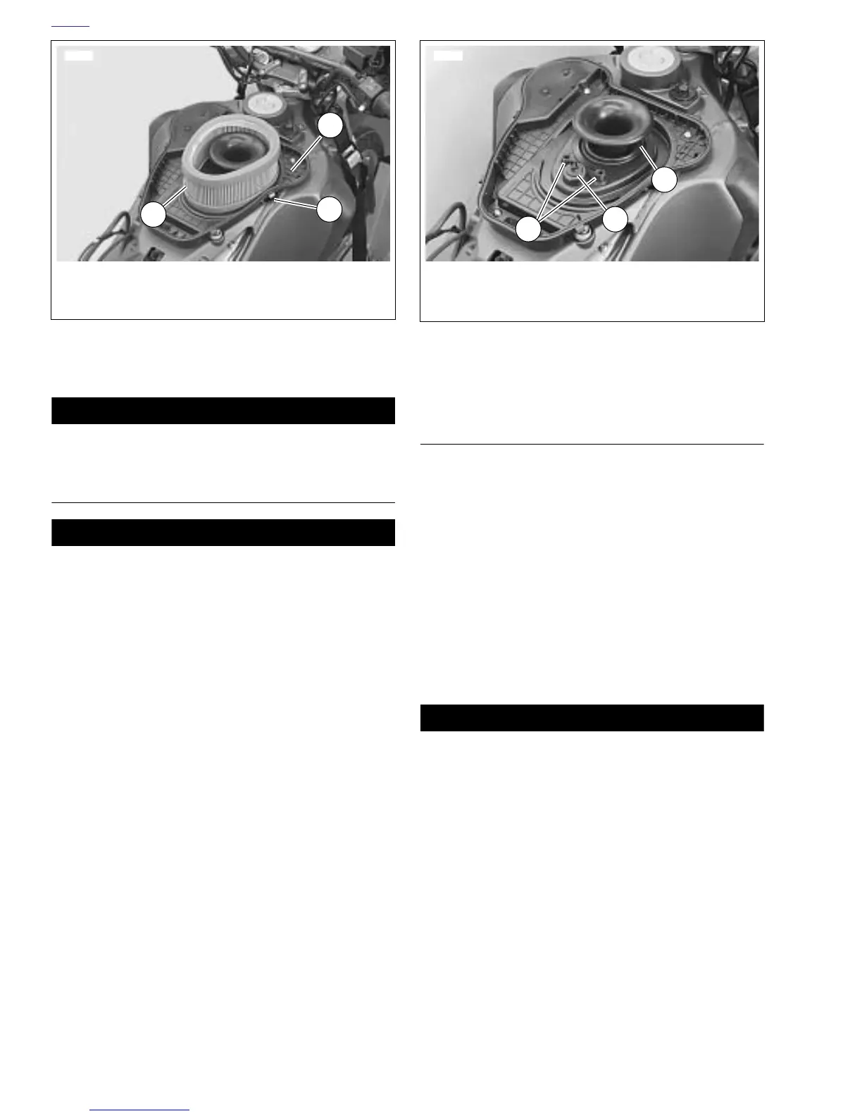
5. See Figure 1-42. Remove the filter element (1) from
base plate (2). Inspect and replace if necessary.
CAUTION
See Figure 1-42. Cover the velocity stack so nothing can
drop into the motor.
CLEANING AND INSPECTION
1WARNING1WARNING
Do not use gasoline or solvents to clean filter element.
Flammable cleaning agents can cause an intake system
fire, which could result in death or serious injury.
(00101a)
1. Check filter element. Hold filter element up to strong light
source. The element can be considered sufficiently clean
if light is uniformly visible through the element.
2. Thoroughly clean base plate and inside of air cleaner
cover.
3. See Figure 1-43. Make sure two crankcase breather
hoses (1) and intake air sensor (2) are captured in base
plate behind velocity stack (3).
INSTALLATION
1. See Figure 1-42. Place filter element (1) on base plate
(2).
2. See Figure 1-41. Position air cleaner cover (1) over base
plate. Make sure air filter remains correctly positioned.
3. Install air cleaner cover by latching six latch tabs (2) to
base plate.
4. For 1200 models verify that the actuator cable and har-
ness are in the grooves on the air cleaner cover.
5. See Figure 1-40. Position fuel vent tube in groove on top
of air cleaner cover and connect to fuel vent valve (7).
Secure vent tube to fuel vent valve with new cable strap.
6. Install intake cover assembly with four fasteners and
nylon washers. Tighten fasteners to 12-36 in-lbs (1.3-
4 Nm).
1WARNING1WARNING
After installing seat, pull upward on front of seat to be
sure it is in locked position. While riding, a loose seat can
shift causing loss of control, which could result in death
or serious injury. (00070a)
7. Install seat. See 2.38 SEAT.
Figure 1-42. Installed Air Cleaner Filter Element
11503
1. Filter element
2. Base plate assembly
3. Air cleaner cover latch tabs (6)
1
3
2
Figure 1-43. Air Cleaner Base Plate Assembly
8373a
1. Breather hoses (2)
2. Intake air sensor
3. Velocity stack
3
2
1