4-10 2007 Buell Firebolt: Fuel System
HOME
BREAKOUT BOX 4.6
GENERAL
The BREAKOUT BOX (Part No. HD-42682) splices into the
main harness. Used in conjunction with a DVOM, it allows cir-
cuit diagnosis of wiring harness and connections without hav-
ing to probe with sharp objects.
INSTALLATION
1. Remove ECM. See 4.30 ELECTRONIC CONTROL
MODULE.
2. Depress latches on each side of connectors [10] (black)
and [11] (gray) and detach connectors from the ECM.
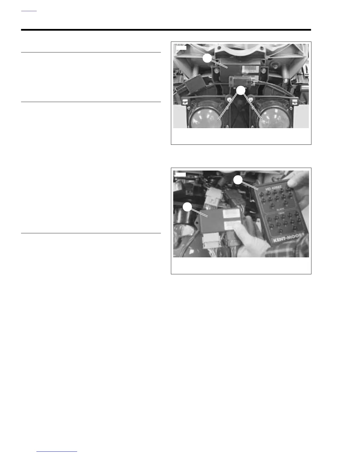
3. See Figure 4-10. Attach Breakout Box (2) to black con-
nector [10].
a. Attach black connector from Breakout Box to corre-
sponding black ECM connector.
b. Attach black connector from the wiring harness to
black connector on Breakout Box.
4. Attach Breakout Box to gray connector [11].
a. Attach gray connector from Breakout Box to corre-
sponding gray ECM connector.
b. Attach gray connector from the wiring harness to
gray connector on Breakout Box.
REMOVAL
1. See Figure 4-10. Depress latches on each side of con-
nectors [10] (black) and [11] (gray).
2. Detach Breakout Box connectors from ECM connectors.
3. Detach Breakout Box connectors from wiring harness.
4. Install ECM. See 4.30 ELECTRONIC CONTROL MOD-
ULE.
Figure 4-9. ECM
Figure 4-10. Installed Breakout Box
1. ECM
2. Headlights
1
2
8428
1. ECM
2. Breakout Box
1
2
8427