2007 Buell Firebolt: Electrical 7-49
HOME
HANDLEBAR SWITCHES 7.16
REMOVAL
NOTE
The individual handlebar switches are not repairable.
Replace switch assembly upon switch failure.
Right Side
1. Remove throttle cables. See 2.23 THROTTLE CON-
TROL.
2. Access right handlebar switch connector [22] under fair-
ing. Remove cable straps. Detach connector [22] from
wiring harness.
3. Detach brake switch connector [121].
Left Side
1. Remove left switch housing mounting fasteners.
2. Unplug the clutch switch [95].
3. Access left handlebar switch connector [24] under fair-
ing. Remove cable straps. Detach connector [24] from
wiring harness.
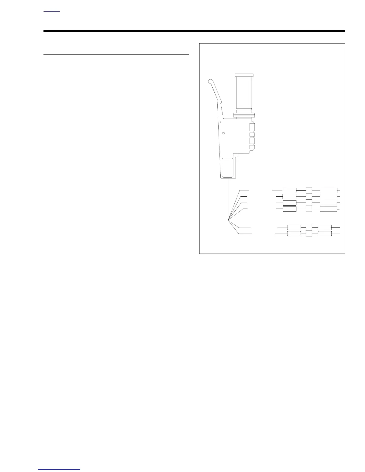
Figure 7-57. Right Handlebar Switch Connection
1
2
1
3
2
4
b1101x7x
Right Handlebar
Switch [22]
Brake Switch [121]
To starter relay
GY GY/O
W/BK
W/BK
W/BK
W/BK
BK/R
BK/R
O
O
R/Y
R/Y
To stoplight
From Ign. relay
To Ign. relay
From Ign. relay
Fused power