2-76 2007 Buell Firebolt: Chassis
HOME
HANDLEBARS 2.27
GENERAL
Firebolt handlebars are a clip-on assembly and are not
adjustable.
REMOVAL
Right Clip-on
1. Remove right switch gear housing. See 7.16 HANDLE-
BAR SWITCHES.
2. Remove front brake master cylinder and grip. See 2.10
FRONT BRAKE MASTER CYLINDER AND HAND
LEVER.
3. See Figure 2-107. Remove right clip-on assembly.
a. Partially loosen clip-on mounting fastener (4).
b. Using a rubber mallet, tap the partially loosened fas-
tener to push the clip-on (2) from the upper right fork
clamp (3). Repeat this procedure until fastener and
clip-on has been removed from fork clamp.
4. Remove clip-on endcap (1).
Left Clip-on
1. Remove left switch gear housing. See 7.16 HANDLE-
BAR SWITCHES.
2. Remove clutch lever assembly. See 2.24 CLUTCH CON-
TROL.
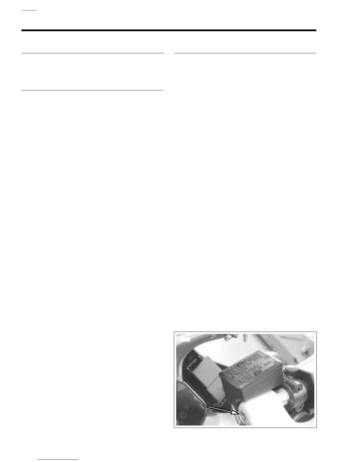
3. See Figure 2-106. Remove clip-on assembly.
a. See Figure 2-107. Partially loosen clip-on mounting
fastener.
b. Using a rubber mallet, tap the partially loosened fas-
tener to push the clip-on (2) from the upper left fork
clamp (3). Repeat this procedure until fastener (4)
and clip-on (2) has been removed from fork clamp.
4. Remove clip-on endcap (1).
INSTALLATION
Right Clip-on
1. Install right switch gear housing.
2. Install right clip-on into right fork clamp and tighten fas-
tener to 24-26 ft-lbs (33-35 Nm).
3. Install front brake master cylinder. Tighten but do not
torque.
4. Install throttle and grip onto right clip-on. See 2.23
THROTTLE CONTROL.
5. Install endcap onto right clip-on.
6. Position brake hand lever to rider preferences and
tighten fastener to 80-90 in-lbs (9-10 Nm). See 2.10
FRONT BRAKE MASTER CYLINDER AND HAND
LEVER.
Left Clip-on
1. Install clutch hand lever assembly onto clip-on. Tighten
but do not torque.
2. Install left switch gear housing. See 7.16 HANDLEBAR
SWITCHES.
3. See Figure 2-107. Install grip and endcap (1).
4. Install left clip-on into upper fork clamp (3) and tighten
fastener (4) to 24-26 ft-lbs (33-35 Nm).
5. See Figure 2-94. Position clutch hand lever to rider pref-
erences and tighten fastener (1) to 60-84 in-lbs (6.8-
9.5 Nm). See 2.24 CLUTCH CONTROL.
Figure 2-106. Handlebar Clip-on Mounting Fasteners
(right clip-on shown)
8355