2007 Buell Firebolt: Fuel System 4-101
HOME
OXYGEN SENSOR 4.33
GENERAL
The oxygen sensor, located in the rear header pipe, monitors
oxygen content in the exhaust gas and converts it to a voltage
reading. This voltage reading is used by the ECM to maintain
the proper air/fuel ratio during closed loop operation.
REMOVAL
1WARNING1WARNING
To prevent accidental vehicle start-up, which could
cause death or serious injury, disconnect negative (-)
battery cable before proceeding. (00048a)
1. Disconnect negative battery cable.
2. Remove intake cover assembly. See 2.34 INTAKE
COVER ASSEMBLY.
3. Remove air cleaner cover assembly. See 4.44 AIR
CLEANER ASSEMBLY.
4. Remove shock absorber. See 2.22 REAR SHOCK
ABSORBER.
5. Remove cooling fan. See 4.38 COOLING FAN.
6. See Figure 4-76. Remove cable straps (2). Unplug 1-
place connector [137] (1).
7. Remove oxygen sensor from exhaust header using
Snap-on Part No. YA8875.
INSTALLATION
1. Apply LOCTITE ANTI-SEIZE LUBRICANT to threads of
sensor.
2. See Figure 4-75. Thread sensor into exhaust header.
Tighten sensor to 40-45 ft-lbs (54-61 Nm).
3. Install cooling fan. See 4.38 COOLING FAN.
4. Install shock absorber. See 2.22 REAR SHOCK
ABSORBER.
5. See Figure 4-76. Connect 1-place connector [137] (1) to
wiring harness.
6. Install cable straps (2).
7. Install air cleaner cover assembly. See 4.44 AIR
CLEANER ASSEMBLY.
8. Install intake cover assembly. See 2.34 INTAKE COVER
ASSEMBLY.
9. Connect negative battery cable.
Figure 4-75. Installed Oxygen Sensor (shock absorber
removed)
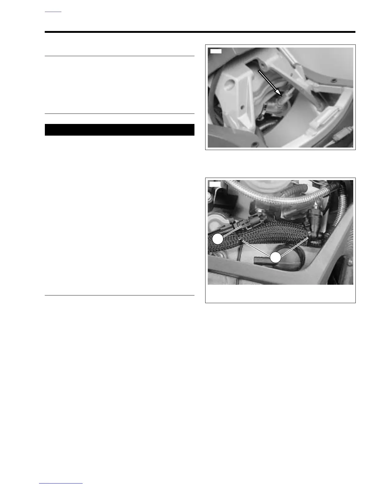
Figure 4-76. Oxygen Sensor Connector [137]
(1200 Models)
1. Oxygen sensor connector [137]
2. Cable straps
1
2
10557