2-66 2007 Buell Firebolt: Chassis
HOME
THROTTLE CONTROL 2.23
REMOVAL/DISASSEMBLY
1. See Figure 2-91. Loosen cable adjuster lock (thick disc)
(3) on each cable.
2. Turn adjusters (thin disc) (3) in direction which will
shorten cable housings to minimum length.
3. Remove fasteners (1) on right switch housing and sepa-
rate housing from handlebar.
4. See Figure 2-92. Remove cables (2, 3) from notches in
front housing (4).
5. Remove ferrules (6) from throttle (7).
6. Remove air cleaner cover and base plate. See 4.44 AIR
CLEANER ASSEMBLY.
7. Disconnect cables from throttle body manifold to remove.
8. Cut cable straps and remove cables.
CLEANING AND INSPECTION
11WARNING1WARNING
Compressed air can pierce the skin and flying debris
from compressed air could cause serious eye injury.
Wear safety glasses when working with compressed air.
Never use your hand to check for air leaks or to deter-
mine air flow rates. (00061a)
Clean all parts except cables in a non-flammable cleaning
solvent. Blow dry with compressed air. Replace cables if
frayed, kinked or bent.
ASSEMBLY/INSTALLATION
1. Route cable as shown in D.1 HOSE AND WIRE ROUT-
ING.
2. Add cable straps as shown in the throttle cable routing in
D.1 HOSE AND WIRE ROUTING.
3. Install throttle grip and position ferrules (6) into cable
wheel (7).
4. Insert idle control into front switch housing.
5. Slide switch housing over throttle.
6. Insert throttle cable into front switch housing.
7. See Figure 2-91. Attach rear switch housing and position
housings on right handlebar by engaging locating pin on
front housing with hole in handlebar. Attach housings
with two fasteners, installing longer fastener on bottom.
Tighten to 25-33 in-lbs (3-4 Nm).
8. Adjust cables. See 1.16 THROTTLE CABLE AND IDLE
SPEED ADJUSTMENT.
9. Install air cleaner assembly. See 4.44 AIR CLEANER
ASSEMBLY.
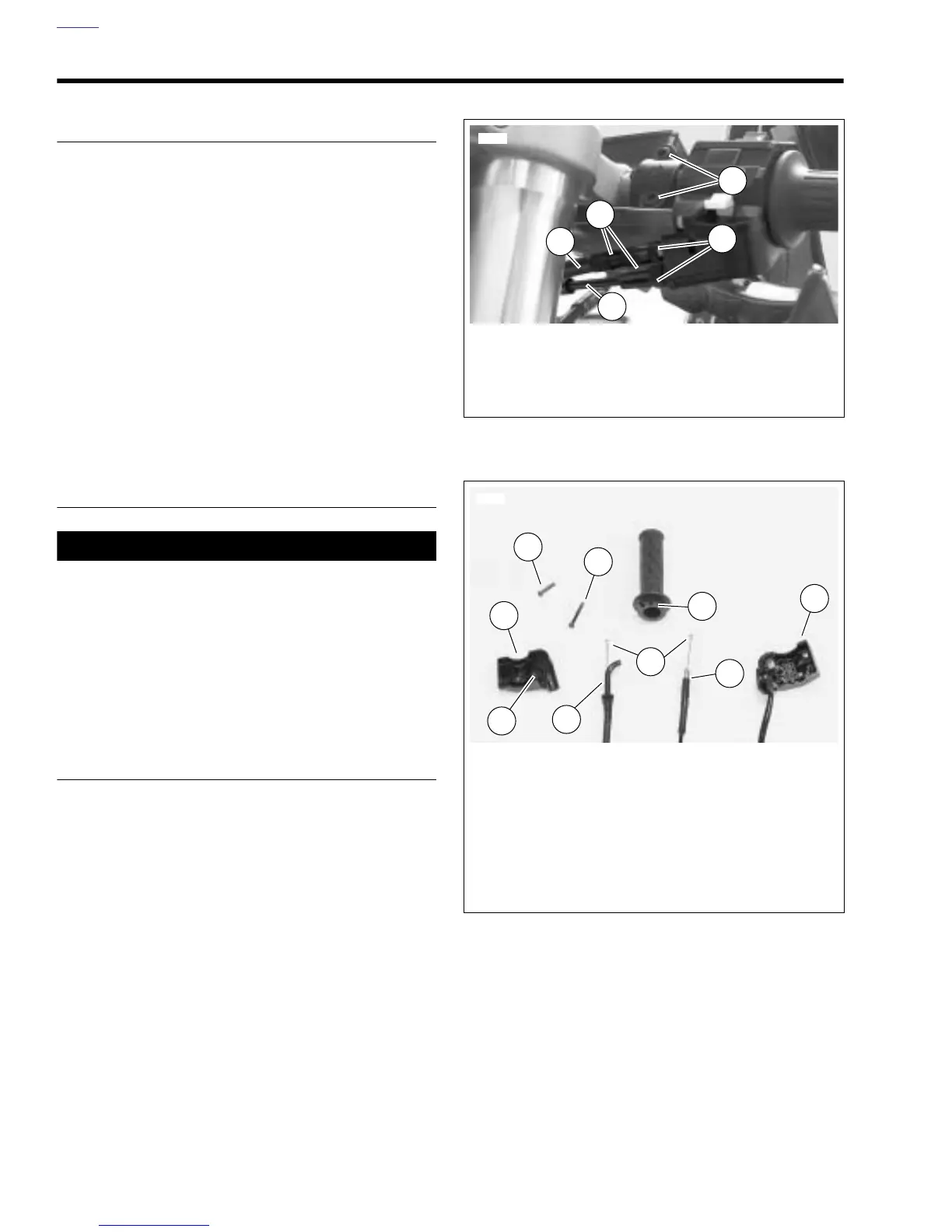
Figure 2-91. Throttle Control Cables
Figure 2-92. Cable Connections
1. Front master cylinder fasteners
2. Adjusters
3. Cable adjuster lock
4. Throttle control cable
5. Idle control cable
8401
1
4
5
3
2
1. Screw (short, top)
2. Idle control cable
3. Throttle control cable with molded end
4. Front housing
5. Screw (long, bottom)
6. Ferrules
7. Cable wheel
8. Rear housing
9. Locating pin
1
7098
4
8
7
5
3
2
6
9