2007 Buell Firebolt: Chassis 2-65
HOME
REMOVAL
1. Remove seat. See 2.38 SEAT.
11WARNING1WARNING
Disconnect negative (-) battery cable first. If positive (+)
cable should contact ground with negative (-) cable con-
nected, the resulting sparks can cause a battery explo-
sion, which could result in death or serious injury.
(00049a)
2. Disconnect and remove battery. See 1.5 BATTERY
MAINTENANCE.
3. Remove tail body work. See 2.36 SUBFRAME TAIL
ASSEMBLY AND BODY WORK.
4. Place a scissor jack under jacking point and raise rear
wheel off ground. For location of jacking point see Figure
2-108.
5. See Figure 2-88. Remove upper shock (5) and lower
shock mount fasteners (6 and 9) and lower shock mount
sleeve (8).
6. Remove rear shock reservoir clamp (2).
7. See Figure 2-89. Cut cable strap.
8. Feed rear shock reservoir through tail section.
9. Remove rear shock.
a. Raise motorcycle up approximately 2 more inches
(51 mm).
b. Remove shock through the top of the tail section
(opening beneath rider seat).
INSTALLATION
1. See Figure 2-88. Install upper shock mount and tighten
fastener (5) to 48-52 ft-lbs (65-70.5 Nm).
2. Install lower shock mount with fasteners, washers (6, 9,
12) and lower shock mount sleeve (8) and tighten to 15-
17 ft-lbs (20.3-23 Nm).
NOTE
Verify that fan spins freely after shock is installed.
3. Feed rear shock reservoir through tail section. D.1 HOSE
AND WIRE ROUTING for correct routing.
a. Loosely install reservoir in clamp.
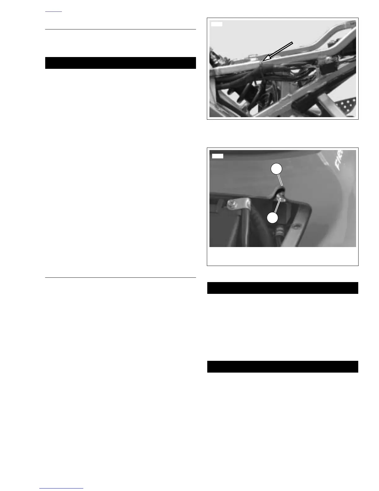
b. See Figure 2-90. Temporarily place upper body work
onto tail section and adjust reservoir placement so
the adjuster screw aligns with bodywork.
c. Tighten clamp on reservoir to 120-144 in-lbs
(13.5-16.2 Nm).
4. See Figure 2-89. Install cable strap.
NOTE
See Figure 2-88. Verify compression adjuster screw is facing
up.
5. Install upper body work. See 2.36 SUBFRAME TAIL
ASSEMBLY AND BODY WORK.
Connect positive (+) battery cable first. If positive (+)
cable should contact ground with negative (-) cable con-
nected, the resulting sparks can cause a battery explo-
sion, which could result in death or serious injury.
(00068a)
6. Install battery by threading positive cable (red) into
threaded hole first tightening to 72-96 in-lbs (8-11 Nm).
See 1.5 BATTERY MAINTENANCE.
After installing seat, pull upward on front of seat to be
sure it is in locked position. While riding, a loose seat can
shift causing loss of control, which could result in death
or serious injury. (00070a)
7. Install seat. See 2.38 SEAT.
Figure 2-89. Cable Strap, Left Side Subframe
Tail Assembly
Figure 2-90. Adjuster Screw Alignment
1. Adjuster screw
2. Adjuster screw alignment hole
1
8354
2
 Loading...


