2007 Buell Firebolt: Engine 3-65
HOME
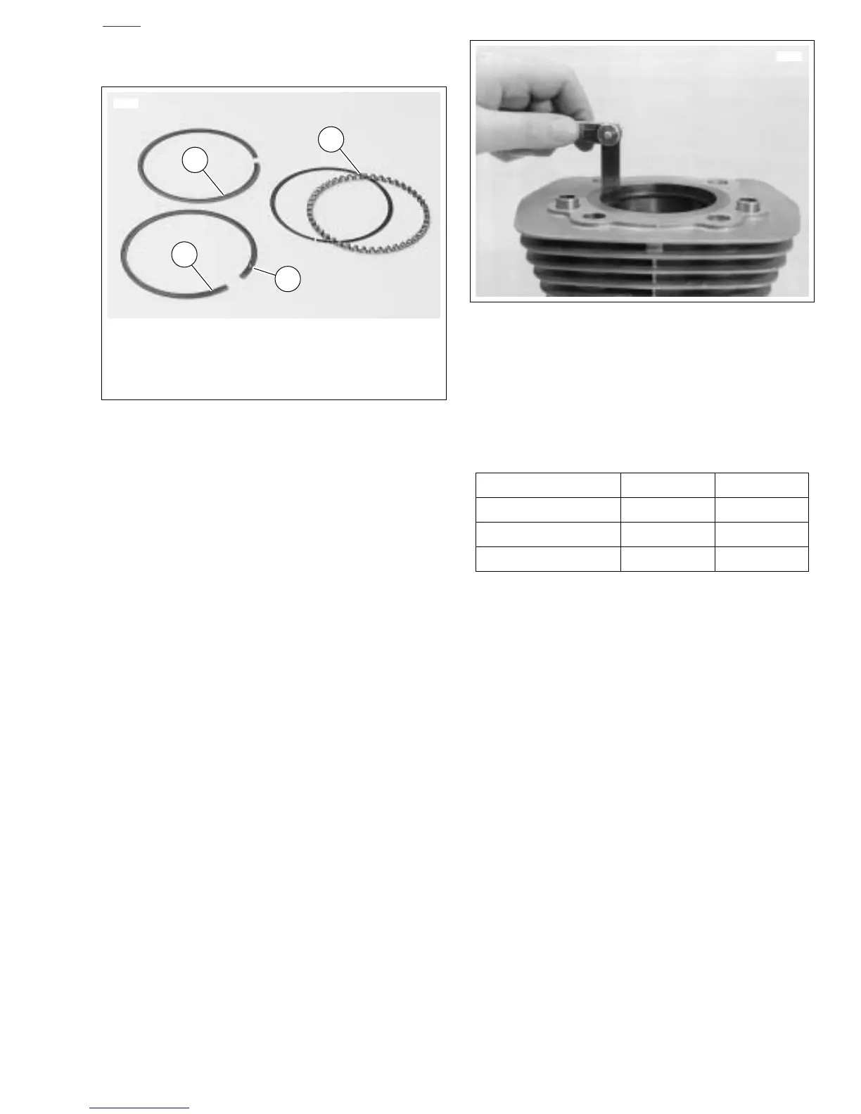
Fitting Piston Rings
NOTES
See Figure 3-91. Piston rings are of two types: compression
(1, 2) and oil control (3). The two compression rings are posi-
tioned in the two upper piston ring grooves. The dot (4) on the
second compression ring must face upward.
1. See Figure 3-92. Insert the new ring into the cylinder,
square it in the bore using the top of the piston and mea-
sure the ring end gap with a feeler gauge. Do not use the
ring if the end gap does not fall within the following spec-
ifications, See Table 3-23.
NOTES
● The same piston may be used if cylinder bore was not
changed, unless it is scuffed or grooved. If re-using pis-
ton, replace piston rings and hone the cylinder walls with
a No. 240 grit flexible hone to facilitate ring seating.
● Piston ring sets must be properly fitted to piston and cyl-
inder:
Figure 3-91. Piston Rings
1. Top compression ring – Install either side up
2. Second compression ring – Install dot toward top
3. Oil control rings
4. Dot
2
1
3
6612
4
Figure 3-92. Measuring Ring End Gap
Table 3-23. Piston Ring End Gap
Ring Type inches mm
Top compression ring 0.010 - 0.020 0.25 - 0.51
2nd compression ring 0.014 - 0.024 0.36 - 0.61
Oil control ring rails 0.010 - 0.050 0.25 - 1.27