2007 Buell Firebolt: Fuel System 4-61
HOME
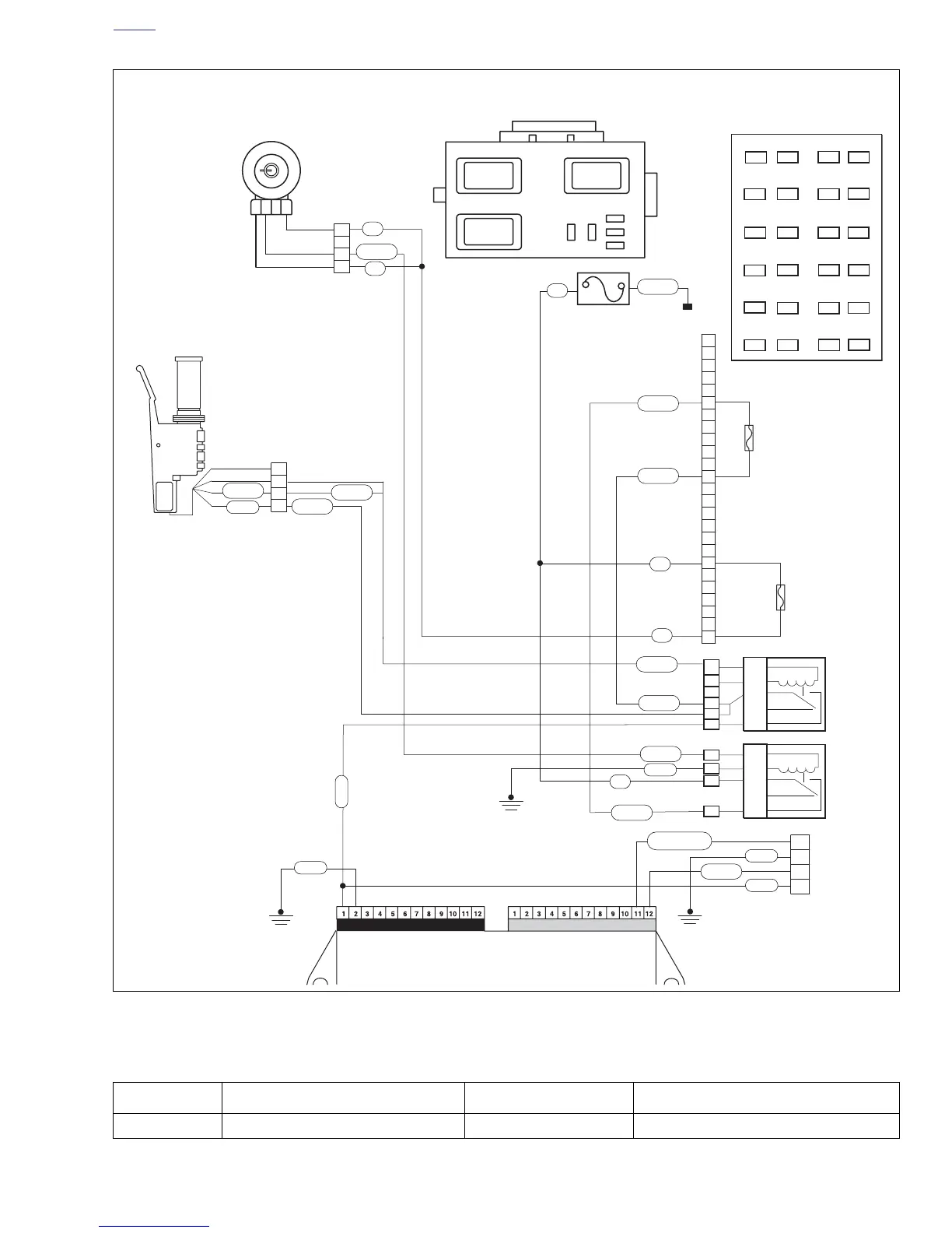
Figure 4-43. Battery Voltage Circuit
1
1
2
2
3
3
4
4
1
2
3
4
1
2
3
4
5
6
7
8
9
10
11
12
13
14
15
16
17
18
19
20
21
22
23
24
9
5
5
4
1
87
87A
30
85
86
19
15
14
11
87
87A
30
85
86
2
ISO
ISOISO
KEY SW.
IGNITION
START
19
20
21
22
23
24
13
14
15
16
17
18
1
2
3
4
5
6
7
8
9
10
11
12
11
Spare
Diode
Bk/Hn/Mflr
Fan
IGN
Acces.
Key Sw
Lights
ECM
Spare
Empty
Empty
Right Handlebar
Switch [22]
GY/O
GY
Ignition
Relay
Key Switch
Relay
Ignition
Fuse
Key Switch
Fuse
Ignition
Switch
[33]
Main Fuse
Electronic Control Module (ECM)
Connector [11]
Connector [10]
Relay
Center
Fuse Block
R
R
W/BK
R
R
R/Y
R/BK
BK
BK
W/BK
GY/O
W/BK
R/BK
GY
GY
BK
LT GN/R
V/R
To Battery
R/BK
R/BK
GY/O
b1083d4x
R
R
Top View
Top View
*ECM [10] Pin 1 also provides
power to fuel pump, both fuel injec-
tors and coil.
Data
Link
Table 4-23. Wire Harness Connectors in Figure 4-43.
NO. DESCRIPTION TYPE LOCATION
[10] ECM (black) 12-place Deutsch in fairing