2007 Buell Firebolt: Fuel System 4-85
HOME
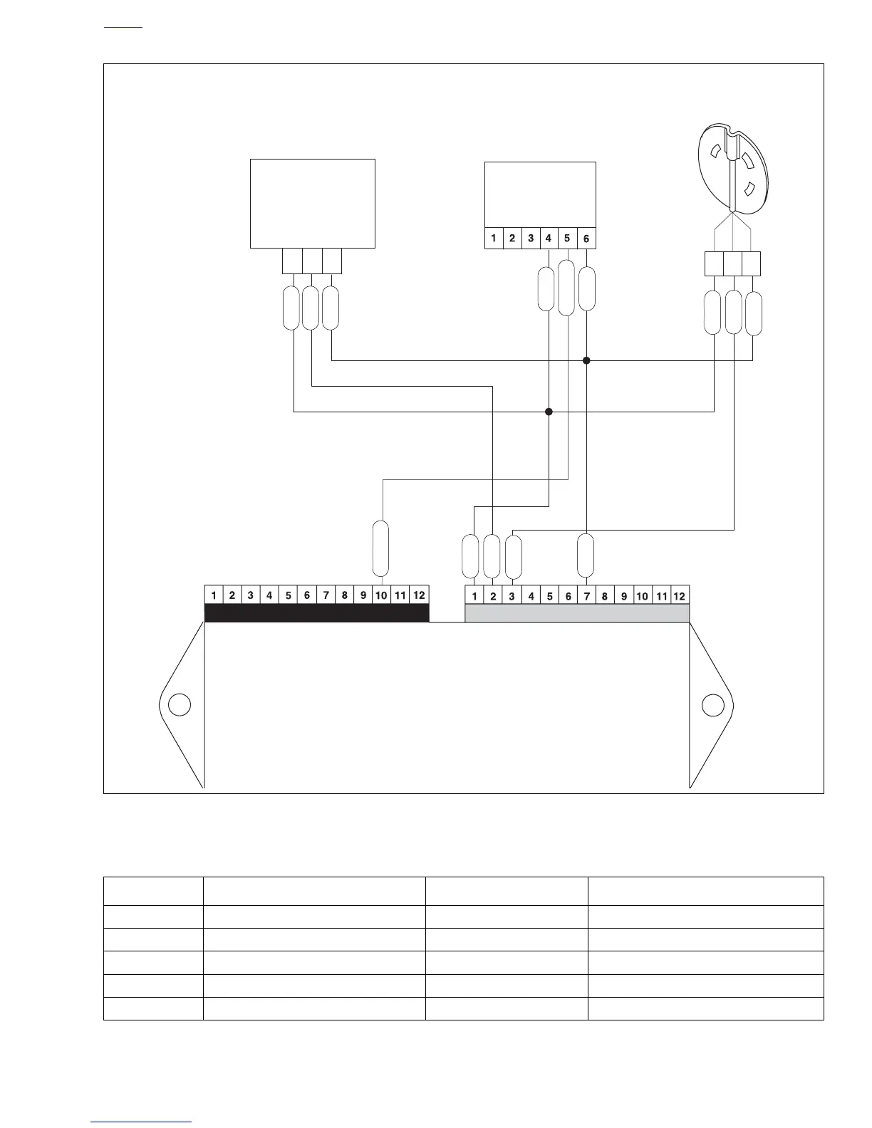
Figure 4-61. Bank Angle Sensor Circuit
1
2
3
C
BA
Throttle
Position
Sensor [88]
R/W
V/Y
BK/W
R/W
BK/W
GN/W
Cam Position
Sensor [14]
R/W = 5 Volt Reference
V/Y = TP Sensor Signal
BK/W = Sensor Ground
R/W
V/Y
GN/W
BK/W
Electronic Control Module
(ECM)
Connector [10]
Connector [11]
LTGN/GY
R/W = 5 Volt Reference
Lt.GN/GY = BAS Signal
BK/W = Sensor Ground
Bank Angle
Sensor
[134]
BK/W
R/W
LTGN/GY
b1112x4x
Table 4-32. Wire Harness Connectors in Figure 4-61.
NO. DESCRIPTION TYPE LOCATION
[10] ECM (black) 12-place Deutsch in fairing
[11] ECM (gray) 12-place Deutsch in fairing
[14] cam position sensor 3-place Deutsch beneath sprocket cover
[88] throttle position sensor 3-place Packard beneath air cleaner baseplate
[134] bank angle sensor 6-place Sumitomo in fairing