4-94 2007 Buell Firebolt: Fuel System
HOME
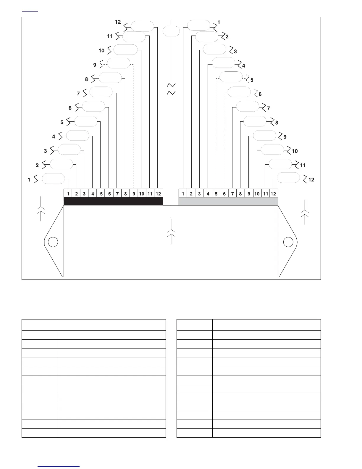
Figure 4-66. ECM Wiring (Interactive Muffler Connector [164] XB12 Models Only)
Connector [10]
b0650x4x
R/W
V/Y
GN/W
V/GY
Y
BK/O
BK/W
W
PK/Y
Lt GN/Y
Lt GN/R
V/R
PK
BK
Lt GN/GY
TN/V
GN/GY
Y/BE
W/Y
BK/Y
BN/Y
BK
GY
Connector [11]
Electronic Control Module
(ECM)
[10A]
[11A]
[10B]
[11B]
BE/O
W
Connector [164A] Interactive Exhaust
[11B]
Table 4-34. Pin Table for
ECM Connector [10] (Black)
PIN FUNCTION
1 Switched ignition
2 System ground A (module)
3 Fuel pump
4 Check engine lamp
5 Injector front
6 Front coil primary
7 Rear coil primary
8 Injector rear
9 Interactive Muffler control feedback
10 Bank angle sensor input
11 System ground B (coil)
12 Tachometer
Table 4-35. Pin Table for
ECM Connector [11] (Gray)
PIN FUNCTION
1 5 volt sensor power
2 Throttle position sensor
3 Camshaft position sensor
4 Oxygen sensor
5 Memory
6 Fan control
7 Sensor ground 1
8 Vehicle speed sensor
9 Engine temperature
10 Intake air temperature
11 Serial data receive
12 Serial data transmit
 Loading...


