6-22 2007 Buell Firebolt: Drive/Transmission
HOME
DRIVE BELT REMOVAL
1. Place a scissor jack under jacking point and raise rear
wheel off ground. For location of jacking point see 2.28
EXHAUST SYSTEM.
2. Remove right side rider footpeg support bracket. See
2.29 FOOTPEG, HEEL GUARD AND MOUNT.
NOTE
The right rear chin fairing fasteners must be removed to
access the front sprocket cover.
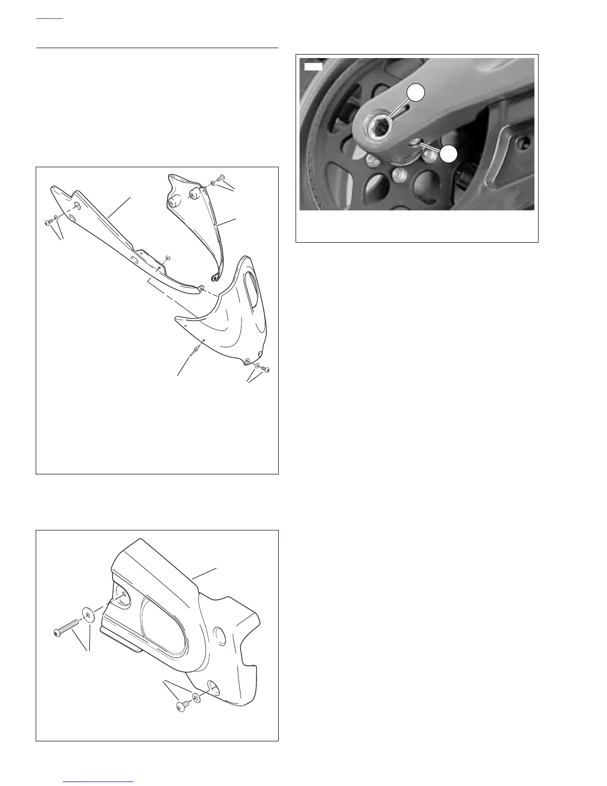
3. Remove right rear chin fairing fasteners. See 2.33 CHIN
FAIRING.
4. See Figure 6-40. Remove sprocket cover. See 2.30.
5. See Figure 6-41. Loosen rear axle pinch fastener (2).
6. Loosen rear axle (1) approximately 15 rotations to allow
partial tension to be removed from rear drive system.
7. Remove idler pulley assembly by removing nuts and
washers. See IDLER PULLEY REMOVAL in 6.6 DRIVE
BELT SYSTEM.
8. Remove swingarm brace. See 2.19 SWINGARM AND
BRACE.
9. Remove lower belt guard. See 2.32 BELT GUARDS.
NOTE
When removing or installing belt, do not bend or twist belt,
partially slide belt onto sprocket and "roll" wheel or belt dam-
age will occur.
10. Slide belt from sprocket and remove.
Figure 6-39. Chin Fairing Assembly
Figure 6-40. Sprocket Cover
b0942x2x
1. Center section
2. Center section fasteners and washers (2)
3. Left section
4. Left section fastener and washer (2)
5. Right section
6. Right section fastener and washer (3)
6
5
4
3
2
1
b0943a2x
1. Sprocket cover fastener and washers
2. S
rocket cover
2
1
1
Figure 6-41. Rear Wheel Mounting, Right Side
11810
2
1. Axle
2. Pinch bolt fastener
1







 To Next Page