7-8 2007 Buell Firebolt: Electrical
HOME
INSTALLATION
1. See Figure 7-4. From beneath upper triple clamp (4),
insert ignition switch assembly into hole. The word “OFF”
stamped on the switch housing should face front of vehi-
cle.
2. See Figure 7-5. Attach ignition switch assembly to upper
triple clamp using ignition switch fasteners (3). USE
LOCTITE 271 (red) on fasteners. Tighten to 18-20 ft-lbs
(24.4-27.1 Nm).
3. See Figure 7-4. Install steering stem cap (3). Tighten but
do not tighten.
4. Install upper clamp on fork assembly.
a. Apply LOCTITE 271 to upper fork clamp pinch fas-
teners (1).
b. Tighten but do not torque upper fork clamp pinch
fasteners.
c. Tighten steering stem cap to 38-42 ft-lbs (52-57
Nm).
d. Install steering stem pinch fastener (2) applying
LOCTITE 271 and tightening to 23-25 ft-lbs (31-34
Nm).
e. Tighten upper fork clamp fasteners to 20-22 ft-lbs
(27-29.8 Nm).
f. Repeat torque sequence in steps d and e.
5. See Figure 7-6. Connect ignition key switch connector
(3) to wiring harness. Install cable strap (2) around igni-
tion switch, fuse block and right handlebar switch wires.
6. Install intake cover assembly. See 2.34 INTAKE COVER
ASSEMBLY.
7. See Figure 7-3. Attach cable straps to upper fork clamp.
a. Install cable strap to the right of ignition switch
securing right hand switch and brake line wires to
upper fork clamp.
b. Install cable strap to the left of ignition switch secur-
ing left hand switch and clutch cable wires to upper
fork clamp.
8. Install negative battery cable.
1WARNING1WARNING
Check for proper headlight operation before riding
motorcycle. Visibility is a major concern for motorcy-
clists. Failure to have proper headlight operation could
result in death or serious injury.
9. Check ignition key switch for proper operation. If opera-
tion fails, reread procedure and verify that all steps were
performed.
1WARNING1WARNING
After installing seat, pull upward on front of seat to be
sure it is in locked position. While riding, a loose seat can
shift causing loss of control, which could result in death
or serious injury. (00070a)
10. Install seat. See 2.38 SEAT.
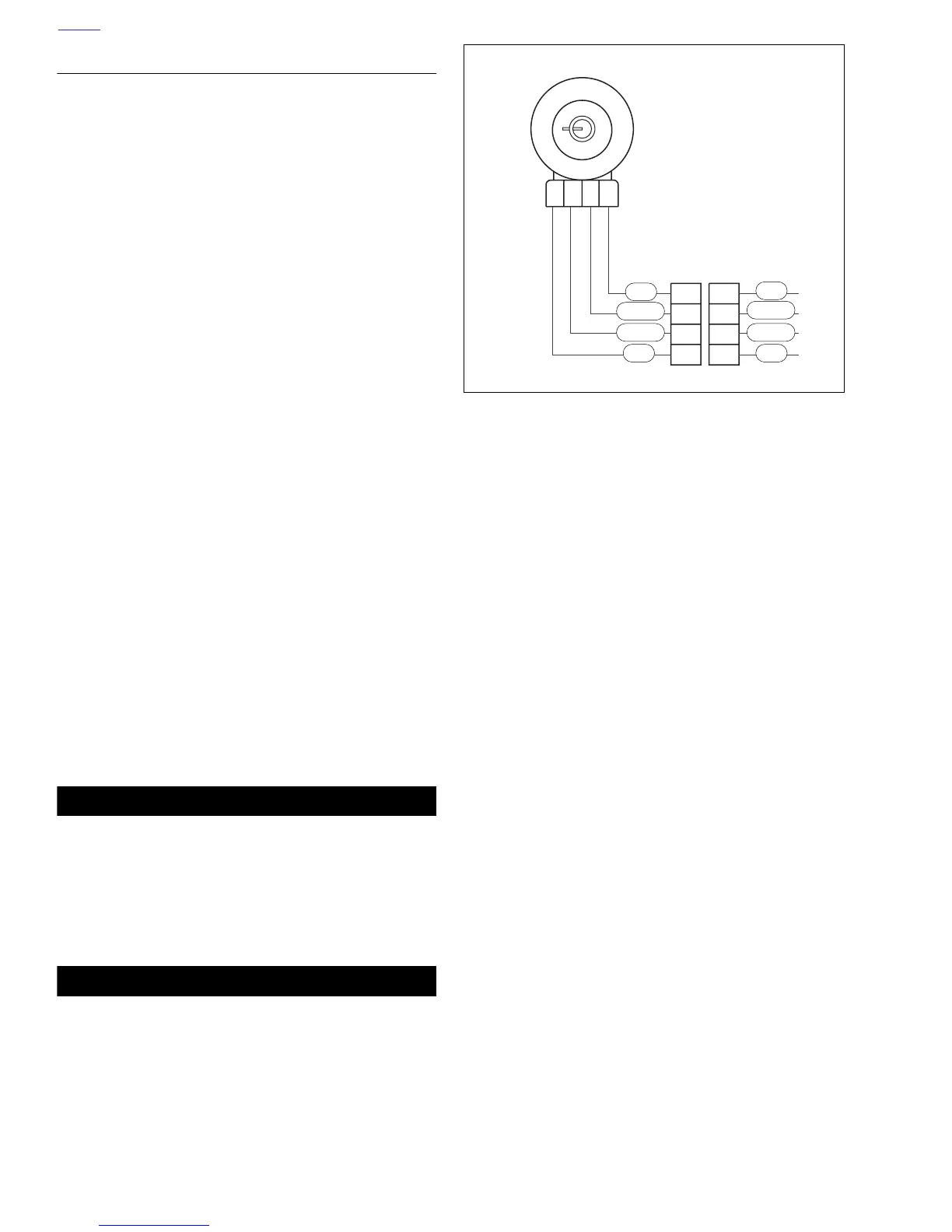
Figure 7-7. Ignition Key Switch Wiring
44
33
22
11
Ignition Key Switch
Ignition Key Switch
Connector [33]
b1110x7x
R/GY
R
R
R
R
R/GY
R/BK R/BK