7-12 2007 Buell Firebolt: Electrical
HOME
DIAGNOSTICS
The reference numbers below correlate with the circled num-
bers in the 7.5 STARTER INTERLOCK flow charts.
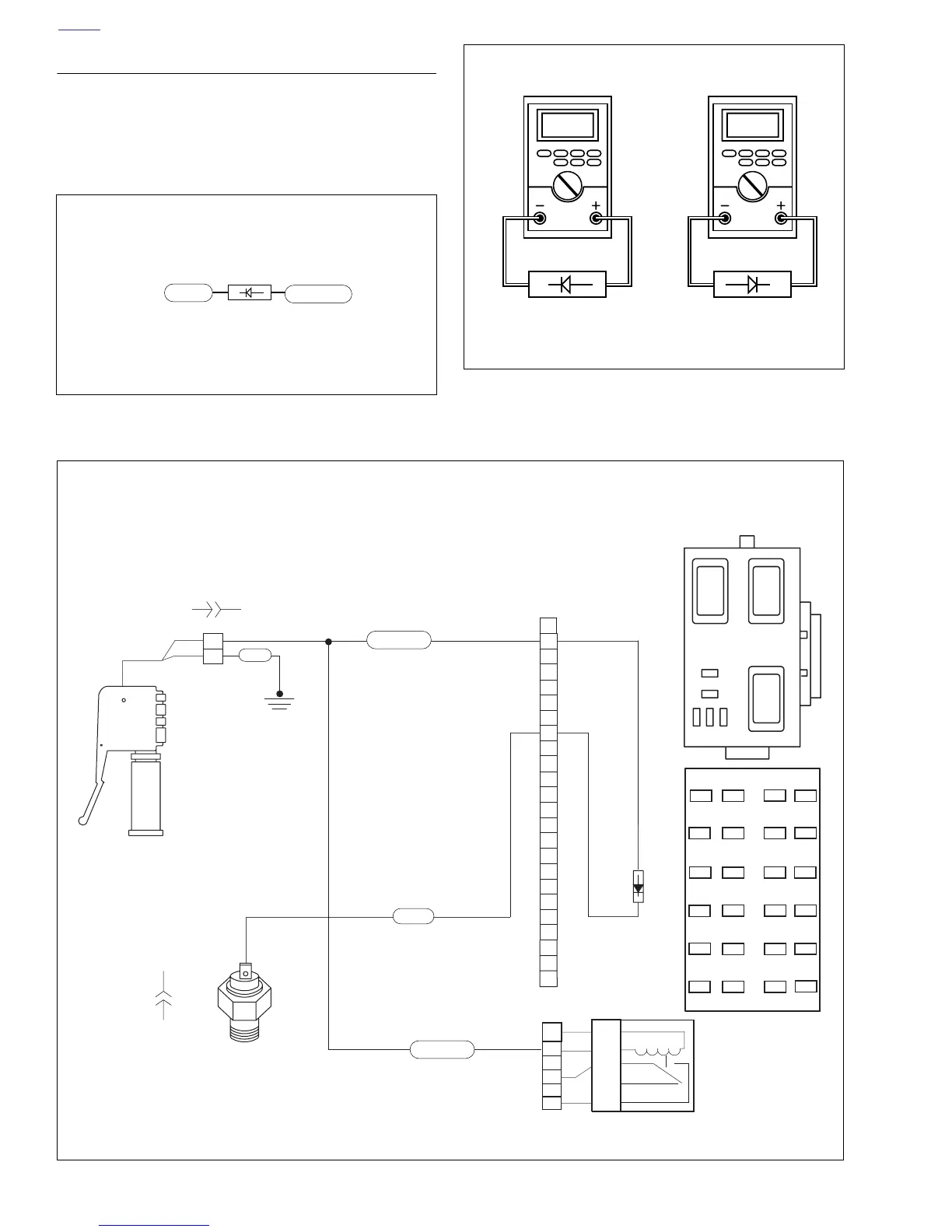
1. Check diode with an ohmmeter as shown in Figure 7-12.
2. Check diode polarity as shown in Figure 7-11.
Figure 7-11. Diode Polarity
b0644x4x
TN/Y
Diode Polarity
TN/LTGN
Terminal (8) Terminal (2)
Figure 7-12. Ohmmeter Diode Test
Continuity Infinite
ohms
b0643x4x
Figure 7-13. Diode Wiring
1
2
1
2
4
5
6
7
8
9
10
11
12
13
14
15
16
17
18
19
20
21
22
23
24
2
6
7
10
87
87A
30
85
86
3
RELAY
CENTER
ISO
ISOISO
KEY SW.
IGNITION
START
19
20
21
22
23
24
13
14
15
16
17
18
1
2
3
4
5
6
7
8
9
10
11
12
11
Spare
Diode
Bk/Hn/Mflr
Fan
IGN
Acces.
Key Sw
Lights
ECM
Spare
Empty
Empty
Neutral
Switch
TN/LTGN
Start
Relay
Diode
TN/Y
BK
b1107e7x
Clutch
Switch
[131A]
[95B]
[131B]
[95A]
TN/LTGN
 Loading...


