2007 Buell Firebolt: Electrical 7-65
HOME
INSTALLATION
NOTE
For more information on wire harness and hose routing, see
D.1 HOSE AND WIRE ROUTING.
1. Feed rear portion of new harness between left front fork
and frame.
2. Continue to feed rear and center portion of harness
between left side of engine and frame.
3. Place connectors in general location of installation.
4. Secure plastic harness holder to left inside portion of
frame using new plastic tree fasteners.
NOTE
Fuel line is installed under engine connector portion of wire
harness.
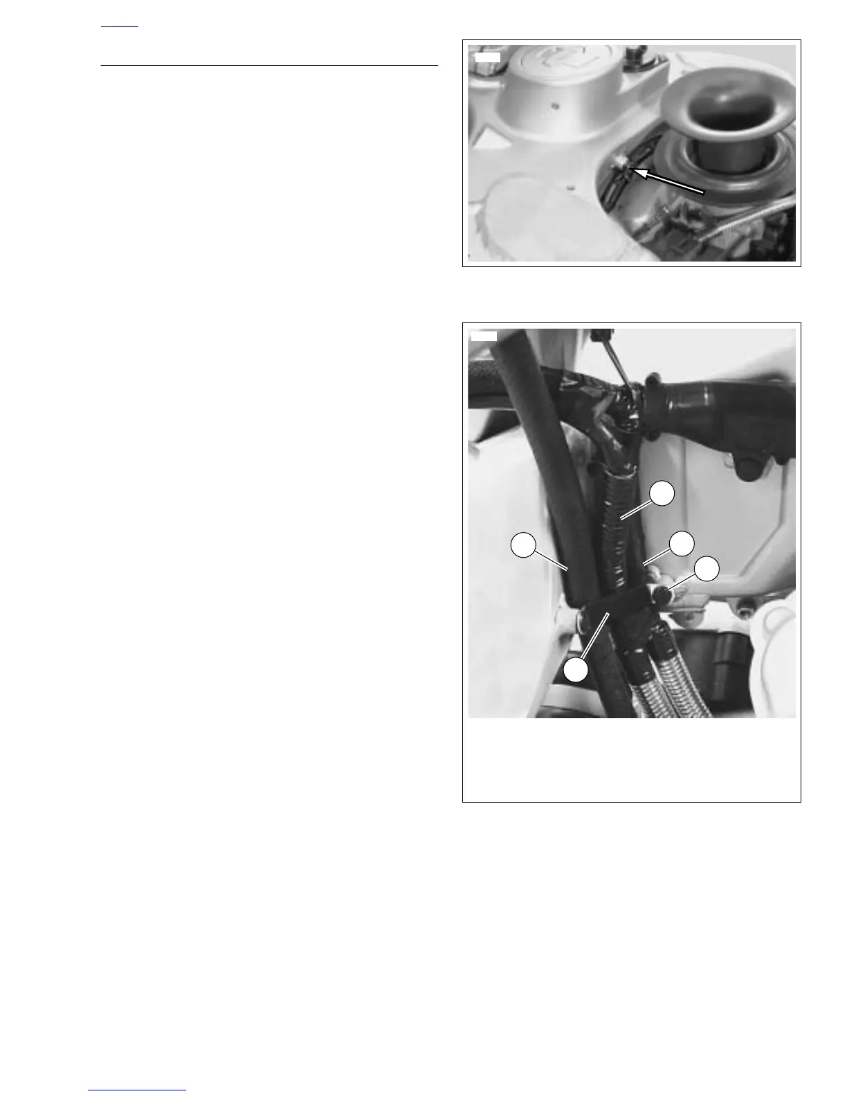
5. See Figure 7-79. Install clamp over portion of harness
that leads to engine connectors. Install clamp as shown
using new plastic tree fastener.
NOTE
On XB12 models be sure to route the interactive exhaust
cable behind the harness strap with the main harness.
6. See Figure 7-80. Route portion of main wire harness that
contains the positive battery cable (3), sprocket cover
wiring (4) and transmission vent hose (2) through corner
mounting tab (1) at rear of frame. Install new plastic tree
fasteners.
7. Connect:
a. Throttle position sensor [88]
b. Intake air temperature sensor [89].
c. O2 sensor [137]
d. Air temperature sensor [90]
e. Fuel injectors [84] & [85].
f. Ignition coil. See 4.32 IGNITION COIL.
8. Install sprocket cover wiring. See 7.25 SPROCKET
COVER WIRING.
9. Install oil pressure switch connector to oil pressure
switch.
NOTE
Snap fuse and relay blocks into mounting brackets before
installing blocks to fairing mounting bracket.
10. Place clamp around fuse block wiring. Mount fuse block
and clamp to fairing support bracket using top fastener
and bottom fastener. Tighten fasteners to 72-96 in-lbs
(8.1-10.8 Nm).
11. Repeat previous steps for relay block.
12. Install steering head clamp around wire harness and
secure clamp to fairing support bracket with loop facing
vehicle. Tighten fastener to 16-18 ft-lbs (21.7-24.4 Nm).
13. Install intake assembly. See 2.34 INTAKE COVER
ASSEMBLY.
14. Connect:
a. headlight connector [38].
b. Front brake switch [121] to right switch housing.
c. Clutch switch [95] to left switch housing.
d. Left switch housing connector [24] and right switch
housing connector [22].
e. Ignition switch [33].
f. Ground terminals on front of steering head.
g. Horn connectors [122].
h. Instrument module connector [39].
Figure 7-79. Wire Harness Clip
Figure 7-80. Wire Harness Strap and Guide
8838
4
2
1
3
1. Mounting strap and guide
2. Transmission vent hose
3. Positive battery cable
4. Sprocket cover wiring
5. Tree fastener (2)
5