2007 Buell Firebolt: Electrical 7-69
HOME
INSTALLATION
1. Mate actuator connector[161B] to actuator.
2. Route harness along channel in air cleaner under frame
and under main wiring harness.
NOTE
If cable is routed in front of the frame lug it will cause the muf-
fler valve to stay open not allowing it to work properly.
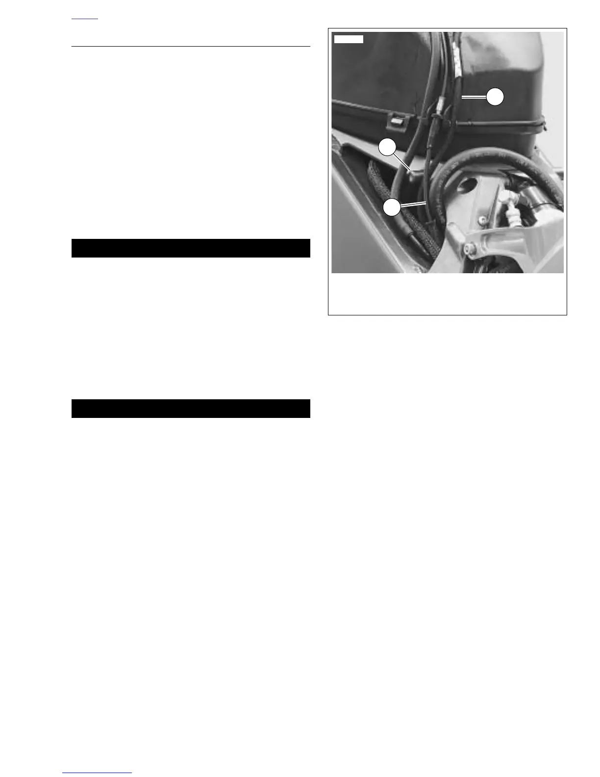
3. See Figure 7-86. Verify that the interactive exhaust cable
(2) is routed behind the frame lug (1) before installing air
intake cover.
4. Mate exhaust actuator harness connector halves [165].
5. Cable wrap were noted.
6. Install ground bolt through main battery ground cable
and actuator ground wire. Tighten to 48-72 in-lbs (5.4-
8.1 Nm).
1WARNING1WARNING
Connect positive (+) battery cable first. If positive (+)
cable should contact ground with negative (-) cable con-
nected, the resulting sparks can cause a battery explo-
sion, which could result in death or serious injury.
(00068a)
7. Connect negative battery cable to battery terminal.
Tighten fastener to 72-96 in-lbs (8-11 Nm).
8. Install subframe tail body work. See 2.36 SUBFRAME
TAIL ASSEMBLY AND BODY WORK.
9. Install intake cover. Tighten fasteners to 12-36 in-lbs
(1.4-4.0 Nm). See 2.34 INTAKE COVER ASSEMBLY.
1WARNING1WARNING
After installing seat, pull upward on front of seat to be
sure it is in locked position. While riding, a loose seat can
shift causing loss of control, which could result in death
or serious injury. (00070a)
10. Install seat and pillion. See 2.38 SEAT.
Figure 7-86. Correct Cable Routing Behind Frame Lug
(Typical)
10567
1. Frame lug
2. Wire harness
3. Cable
1
3
2







 To Next Page