21
Installation
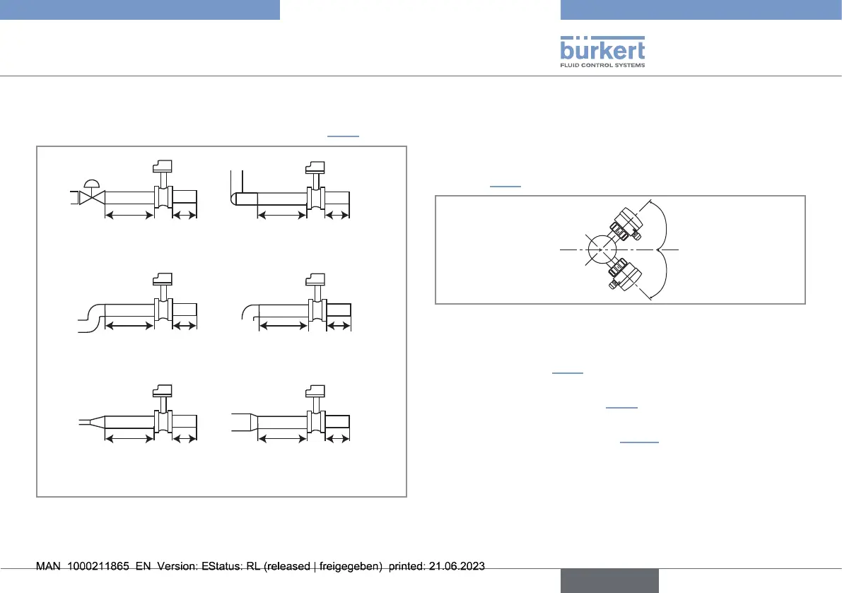
→ Install the device on the pipe to have the upstream and
downstream distances respected according to the design of
the pipes, refer to standard ENISO5167-1 and Fig.7:
50 x DN 5 x DN
40 x DN 5 x DN
25 x DN 5 x DN 20 x DN
18 x DN 5 x DN 15 x DN 5 x DN
With control valve
Pipe with 2 elbows at 90°
in 3 dimensions
Pipe with 2 elbows at 90° Pipe with 1 elbow at 90° or
1 T-piece
With pipe expansion With pipe reduction
Fig.7:
Upstreamanddownstreamdistancesdependingonthe
designofthepipes.
→ Respect the following additional mounting conditions to
ensure that the measuring device operates correctly:
- We recommend to install the device at a 45° angle to the
horizontal centre of the pipe to prevent deposits on the
electrodes and false measurements due to air bubbles
(seeFig.8);
45°
45°
Fig.8: Mountingangleonthepipe
- Ensure that the pipe is always lled in the section around
the device (see Fig.9).
- When mounting vertically ensure that the ow direction is in
an upward direction (see Fig.9).
- Prevent the formation of air bubbles in the pipe in the sec-
tion around the device (see Fig.10).
- Always mount the device upstream a possible injection
point in the pipe of a high-conductivity uid (for example:
acid, base, saline, ...).
english
Type 8041