20
The setup & service menu
1>Config 5 Maint
2 Interfaces
3 Ions
4 Test Hardware
The Test Hardware menu
This diagnostic mode enables the hardware integrated with the
flame photometer to be tested.
Selecting 4>Test Hardware shows the following screen:
1>LED etc
2 V+T
3 KeyMatrix
4 OTA Raw
If a Service Key has been entered (Refer to Section 5.2) an
additional option is displayed
1>LED etc 5 Relays
2 V+T
3 KeyMatrix
4 OTA Raw
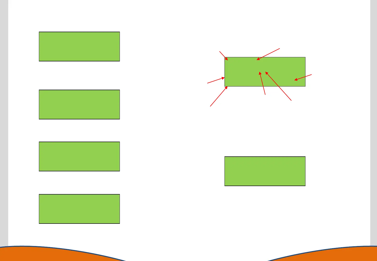
Selecting 1>LED etc shows the following screen:
LED: 01 = 1
Flame: 097% (1)
Fan : 0
UTube:OK GasFB:0
LED: 01 = 1
Flame: 097% (1)
Fan : 0
UTube:OK GasFB:0
Cycles through 01 to 11 as status and
warning LED’s are illuminated.
Changes from 0 to 1 with each
LED test cycle.
Indicates Flame
output level (%)
Changes from 0
to 1 & 2 as
Flame output
increases
Shows Gas Control
Solenoid status:
0 = Closed
1 = Open
Shows Fan status:
0 = OFF, 1 = ON
Shows U Tube Sensor status:
OK or ERROR based on the
position of the sensor at the
time. ERROR indicates a low
level.
This can be used to identify a failed LED, check Fan and Gas Solenoid
supply status and check the operation of the U Tube Sensor
Selecting 2>V+T shows the following screen
5v = 5.00V OTA=26.9˚
11v=11.0V CPU=23
24v=24.0V AIR=24.0
Alarm(0.5) CHY=18.2
This screen (Voltages and Temperatures) shows the Power Supply voltages and
internal temperatures in real time:
OTA (Optical Train Assembly) is the temperature within the OTA module of the
instrument.
CPU (Central Processing Unit) is the current temperature of the central
processor.
AIR (Air Circuit) is the current temperature of the internal air supply.