58
Replacing the Gas Regulator
The gas regulator contains no user serviceable parts. DO NOT
attempt to disassemble the gas regulator.
Note: It is recommended that the OTA is removed before
attempting the removal of the Gas Solenoid to aid with access.
Removal of the Marshalling board will be required during this
process.
1. Gain access to the instrument enclosure as previously
described.
2. Remove the OTA as previously described.
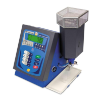
3. Remove the 2 solenoid fixing screws using a T10 Torx driver.
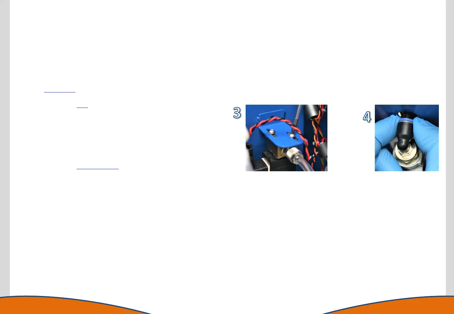
4. Locate the gas regulator connecting collar and gently pull
backwards on the collar, this will disengage the teeth holding
the solenoid tube in location. With the collar pulled back the
solenoid can be pulled in the opposite direction to disconnect
the assembly from the regulator. The solenoid can be left loose
in the enclosure.
5. Remove the Marshalling PCB.
6. Remove the screws and nuts that secure the gas regulator using
a T25 Tox Driver and 8mm A/F spanner. The gas regulator
(including the plastic mounting bracket) can be removed from
the chassis.
7. Reassemble in reverse order ensuring all connectors and tubing
are correctly and firmly attached and that wiring and tubing is
not snagged or pinched.
It is essential that a leakage check is performed using a soap solution
or BWB leak detection solution once the unit is put back to functional
condition, but before replacing the Front Panel and Top Cover
securing screws. Initiate a flame start sequence allowing the solenoid
to pass gas, lower the Front Panel and check all gas connections for
leaks whilst flame is alight. Once all connections have been confirmed
as free from leaks, refit and secure the Front Panel and Top Cover.