60
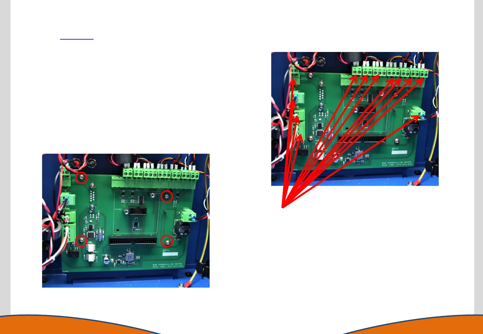
Replacing the Marshalling Board (PCB)
Disconnect all connectors
including the ribbon cable
(already shown removed)
1. Gain access to the instrument enclosure as previously
described.
2. Remove any USB or RS232 connections from the rear of the
instrument.
3. Disconnect all connections from the marshalling board.
4. Remove the 4 retaining screws using a T10 torx driver.
5. Once removed from the housing the AFHS/ Printer Interface
PCB can be removed (if fitted), fit this to the new marshalling
board.
6. Replace the marshalling board.
7. Reassemble the instrument in reverse order.