B-3cab Produkttechnik GmbH & Co KG
Pin Assignment of the Parallel Interface Connector
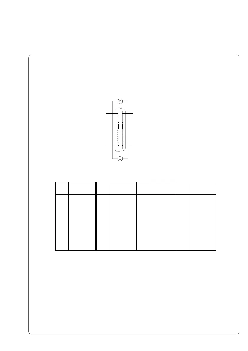
The printer provides a 36 pin connector for the parallel interface.
Table B-2 Signals of the Parallel Interface
Fig. B-3 Parallel Interface Connector (rear of the printer)
Parallel Interface Cable
The cables for parallel interface connections are standard parallel cables.
If problems occur, please contact the manufacturer of your computer on the pin
assignment of the computer's parallel interface. Use the pin assignment of the
printer as shown in Table B-2 to obtain a compatible cable.
Pin Signal Pin Signal Pin Signal Pin Signal
1 /STROBE 10 /ACKNLG 19 GND 28 GND
2 DATA 0 11 BUSY 20 GND 29 GND
3 DATA 1 12 PE 21 GND 30 GND
4 DATA 2 13 SLCT 22 GND 31 /INIT
5 DATA 3 14 /AUTOFD 23 GND 32 /FAULT
6 DATA 4 15 nc 24 GND 33 nc
7 DATA 5 16 GND 25 GND 34 nc
8 DATA 6 17 Chassis 26 GND 35 nc
9 DATA 7 18 +5V 27 GND 36 /SLCTIN
Pin 19
Pin 36Pin 18
Pin 1
Appendix B - Pin Assignment of the Interface Connectors

 Loading...