A-8 cab Produkttechnik GmbH & Co KG
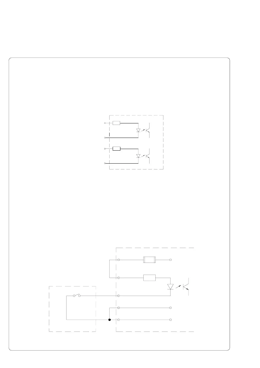
Circuit Diagram of Inputs
The XSTART and XFEH inputs are optocouplers with a current limiting resistor
of 2.2kΩ giving a voltage of 24V in the input circuit.
For each signal X[IN] there is a separate reverse line X[IN]R via the plug
connector. From that, the following matching pairs of signals result :
Corresponding to the operation mode input STA (PIN13) must be connected
with GND (PIN12) or not.
The external device (trigger switch, external control) to be connected must be
equipped with a 15 pin SUB-D connector.
Examples for External Circuits
Fig. A-4 Example with trigger switch
Trigger switch Present sensor electronics
8
13
GND
STA
15
24P
1 XSTART
9 RXSTART
PIN1 - XSTART
PIN9 - RXSTART
PIN2 - XFEH
PIN10 - RXFEH
Appendix A - Operation in Peel-off Mode
Fig. A-3 Internal circuit of the inputs XSTART and XFEH

 Loading...