A-10 cab Produkttechnik GmbH & Co KG
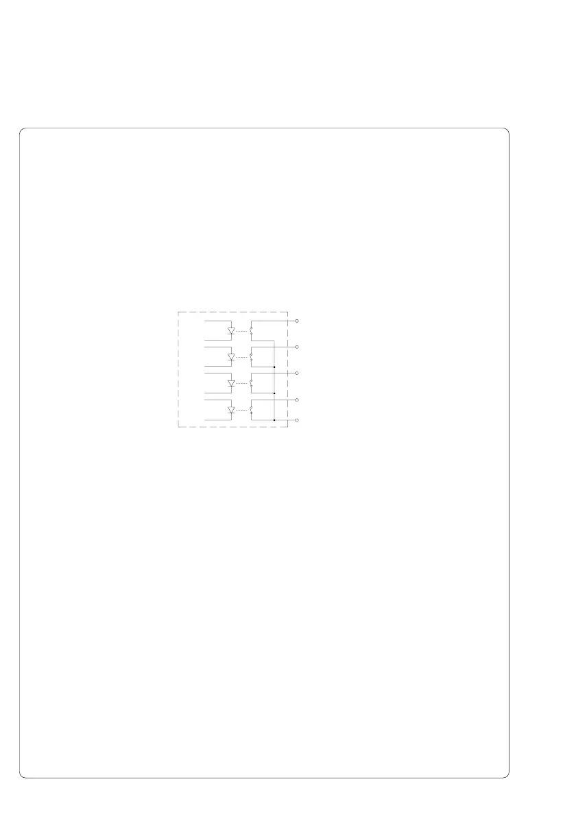
Fig. A-7 Internal Circuits of the Outputs
Circuit Diagram of Outputs
All outputs are recognized through solid state relays Their outputs are
connected to one another on one-side. The joint line is lead to the plug
connector as a RÜL signal.
The switch function of the outputs is to open or close the contact between the
joint line RÜL and the respective output.
Electrical requirements : U
max
= 42V
I
max
= 100mA
PIN4 - XESP
PIN5 - XEDG
PIN6 - XDNB
PIN7 - XEDST
PIN14 - RÜL
Appendix A - Operation in Peel-off Mode
 Loading...