Calix ODC-10 Installation Guide
37
Proprietary Information: Not for use or disclosure except by written agreement with Calix.
© 2001-2003 Calix. All Rights Reserved.
Install and test rectifier modules
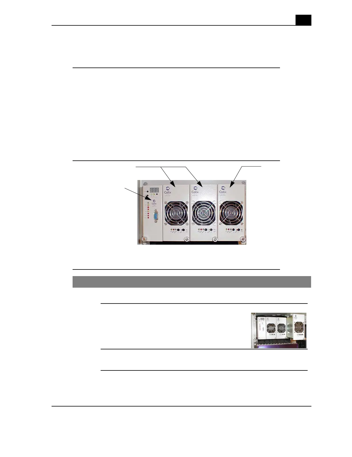
Description of the rectifier shelf
The Calix rectifier shelf contains an alarm control unit on the left and space for three
rectifier modules on the right. Each rectifier module has its own alarm and status
indicators.
A full rectifier shelf, with three rectifier modules, provides a -48VDC power source (30
Amps). Normal operation for the ODC-10 cabinet uses two rectifier modules (20 Amps).
The optional third rectifier module provides faster battery recharge. The modular design
makes the rectifier simple to install and maintain. Each hot-swapable module slides in and
plugs into place.
Location of the rectifier and components
Procedure to install or replace a rectifier module
Step Action
1.
Unbolt and remove the cover plate (or module to be replaced).
2.
Slide the new module into the slot.
3.
Tighten the front bolt to secure the module in place.
Alarm control unit
Rectifier modules 1-2 Rectifier module 3
(optional)