300
500
450
p.
5 - Manual code:
119BJ04EN v.
1 02/2015
© CAME Cancelli Automatici S.p.A. - The data and information in this manual may be changed at any time and without notice..
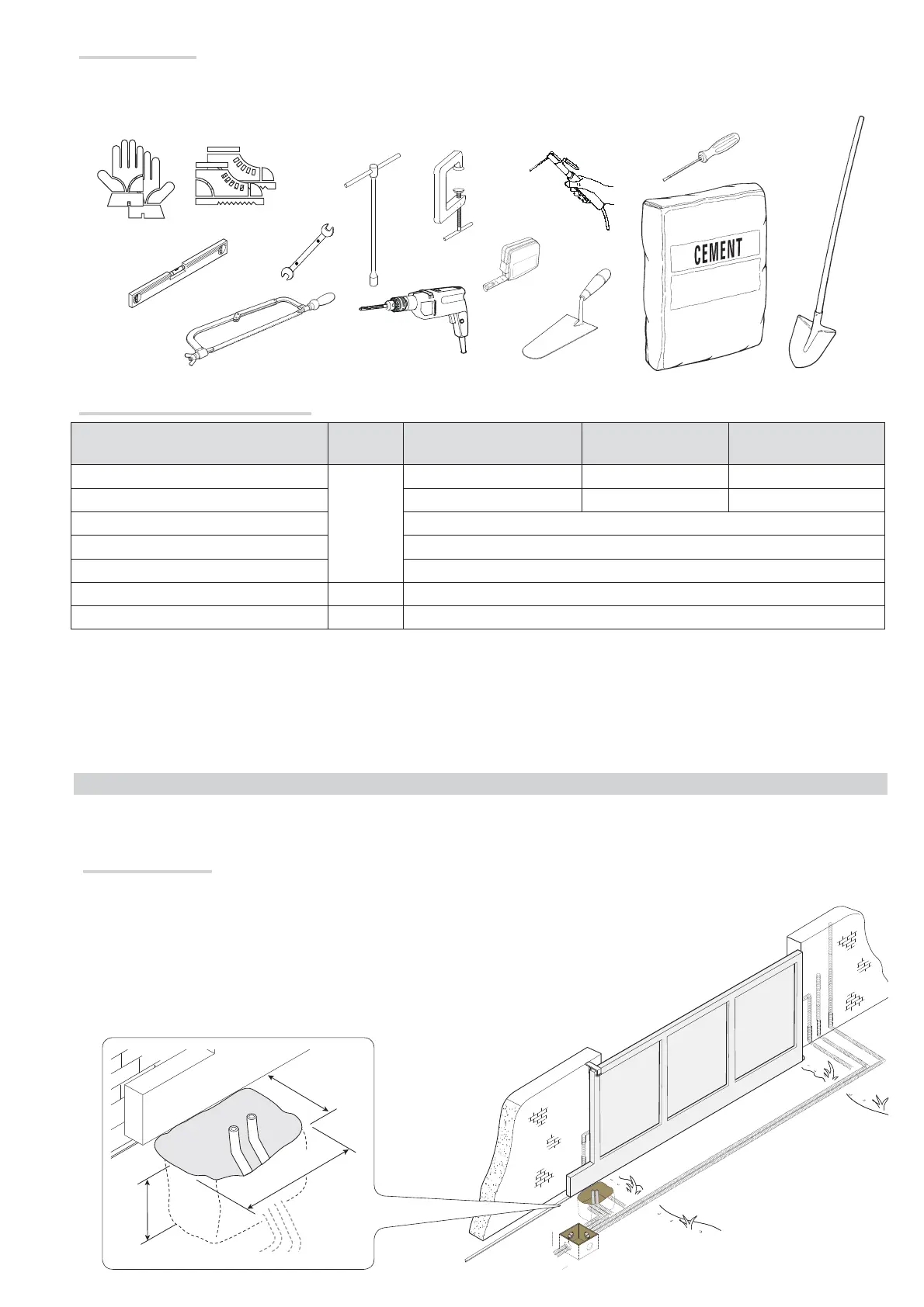
Tools and materials
Make sure you have all the tools and materials you will need for installing in total safety and in compliance with applicable regulations. The figure shows
some of the equipment installers will need.
INSTALLATION
⚠
The following illustrations are mere examples in that the space for anchoring the operator and accessories varies depending on the installation
area. It is up to the installer to find the most suitable solution.
Corrugate tube laying
Dig a hole for the foundation frame.
Set up the corrugated tubes needed for making the connections coming out of the junction pit.
For connecting the gearmotor we suggest using a Ø 40 mm corrugated tube and Ø 25 mm tubes for the accessories.
The number of tubes depends on the type of system and the accessories you are going to fit.
Cable types and minimum thicknesses
Connection Cable type
Cable length
1 < 10 m
Cable length
10 < 20 m
Cable length
20 < 30 m
Control panel power supply 230 V AC
FROR CEI
20-22
CEI EN
50267-2-1
3G x 1.5 mm
2
3G x 2.5 mm
2
3G x 4 mm
2
230 V AC Flashing light 2 x 0.5 mm
2
--
Photocell transmitters 2 x 0.5 mm
2
Photocell receivers 4 x 0.5 mm
2
Command and safety device 2 x 0.5 mm
2
Antenna RG58 max 10 m
Paired connection or CRP UTP CAT5 max 1000 m
If cable lengths differ from those specified in the table, establish the cable sections depending on the actual power draw of the connected devices
and according to the provisions of regulation CEI EN 60204-1.
For multiple, sequential loads along the same line, the dimensions on the table need to be recalculated according to the actual power draw and
distances. If connecting products that are not contemplated in this manual, see the literature accompanying said products