3
1
5
2
6
4
13
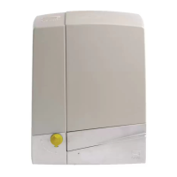
STYLO-BS
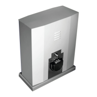
STYLO-BD
7
8
9
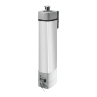
STYLO-ME
STYLO-RME
12
10
11
Page
6 - Manual FA01806-EN - 01/2024 - © CAME S.p.A. - The contents of this manual may change, at any time, and without notice. - Translated original instructions
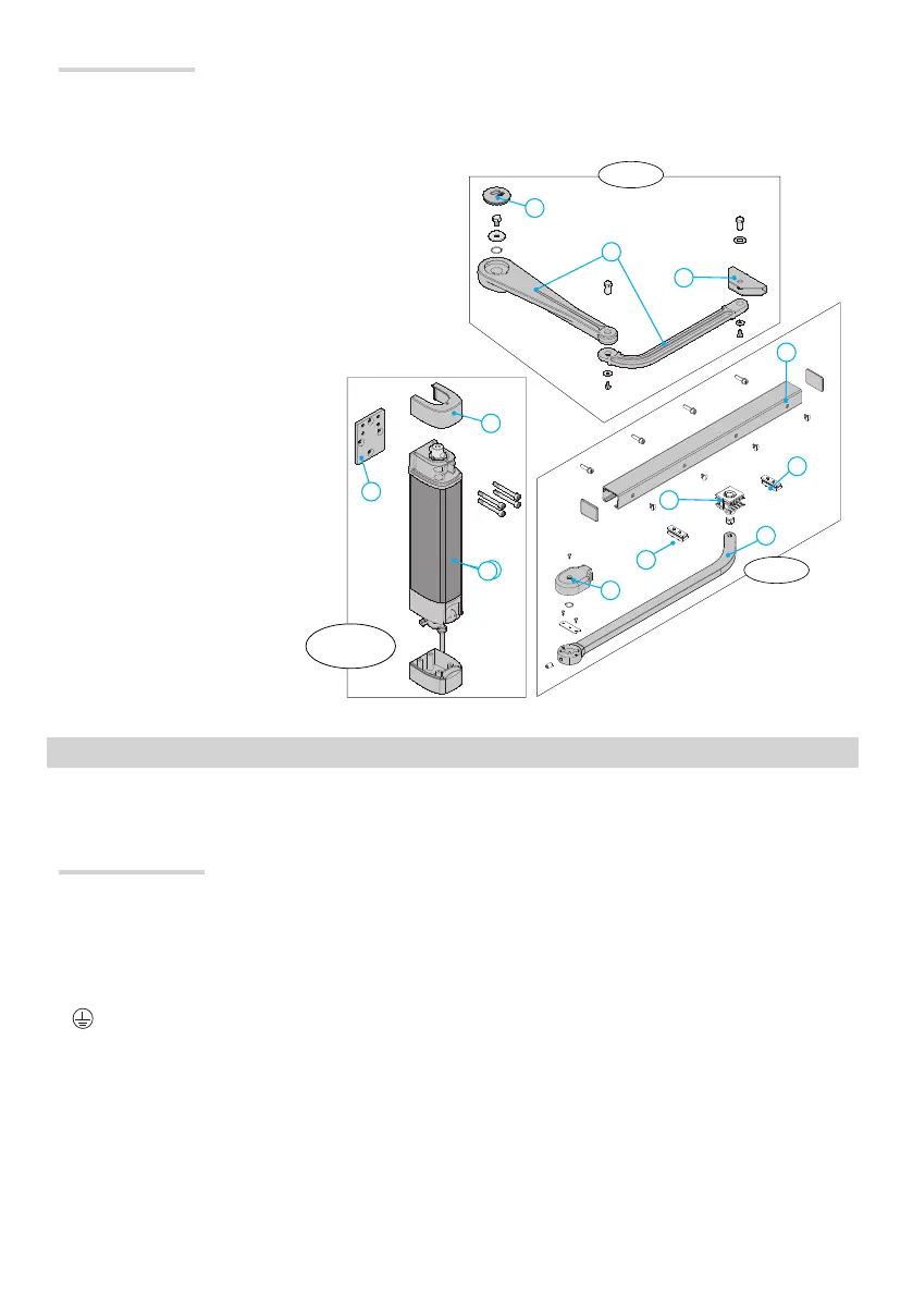
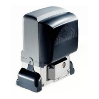
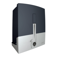
1. Main body of the gearmotor
2. Upper cap
3. Lower cap
4. Hinged arm
5. STYLO-BS arm mounting bracket
6. Gearmotor mounting bracket
7. STYLO-BS cover
8. STYLO-BD cover
9. Slide guide
10. Opening stop
11. STYLO-BD slide rail
12. Closing stop
13. Straight arm
Main components
⚠
Before installing the operator:
• make sure you have set up a suitable dual pole cut off device along the power supply that is compliant with the installation
rules. It should completely cut off the power supply according to category III surcharge conditions (that is, with minimum contact
openings of 3 mm);
• Prepare suitable piping and ducts for routing the electrical cables, ensuring protection against mechanical damage;
•
Make sure that any connections within the container (made to ensure the continuity of the protection circuit) are fitted with
additional insulation compared to the other internal conductor parts;
• Make sure the gate structure is sturdy enough, that the hinges are in proper working order and that there is no friction between
the moving and fixed parts;
• Make sure there are opening and closing mechanical stops.
SYSTEM FEASIBILITY
Preliminary checks
⚠
Installation must be carried out by qualified and experienced personnel in compliance with applicable regulations.