DA
C
i
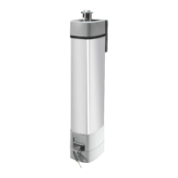
STYLO-BS
STYLO-BD
DA
C
STYLO-BS
56
80
12
404012
4 x ø 8,5
75
60
100
18
2 x ø 6,5
Page
8 - Manual FA01806-EN - 01/2024 - © CAME S.p.A. - The contents of this manual may change, at any time, and without notice. - Translated original instructions
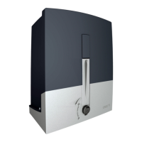
Examples of applications
i = 300 mm max
with 90° opening
Gate-leaf opening (°) A (mm) C (mm) D (mm)
90 90 0÷180 450
90 130 180 450
120 170 0 450
Gate-leaf opening (°) A (mm) C (mm) D (mm)
90 90 0÷200 400
90 230 180 300
135 230 0 300
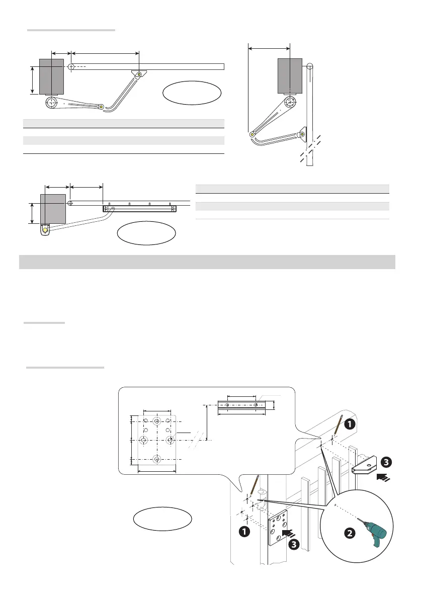
INSTALLATION
⚠
The following illustrations are only examples, given that the space for securing the operator and accessories varies depending
on the overall dimensions. The installation technician is responsible for choosing the most suitable solution.
Preparation
Set up corrugated tubes for the connections coming from the junction box.
N.B. the number of tubes depends on the type of system installed and any accessories.
Securing the brackets
STYLO-BS
Trace all axes and
dimensions, respecting
the levels shown in the
drawing , drill the marked
points , then secure the
gearmotor anchoring bracket
to the wall or post as well as
the arm mounting bracket to
the gate.
Note: the illustrations are
mere examples, it is up
to the install to choose
the most suitable solution
depending on gate leaf type
and thickness.
 Loading...