18
Room Air, Vent Terminal Clearances
A
Clearance above grade, veranda, porch, deck, or
balcony
B
Clearance to window or door that may be opened
4’ (1.2 m) below or to side of
opening; 1’ (30 cm) above
opening
Clearance to window or door that may be opened
Clearance to permanently closed window
Clearance to unventilated soffit
Clearance to outside corner
Clearance to inside corner
H
Clearance to each side of center line extended above
meter/ regulator assembly
36” (91 cm) within a height of
15’ (4.5 m) above the meter/
Clearance to service regulator vent outlet
J
Clearance to non-mechanical air supply inlet to
building or the combustion air inlet to any other
appliance
4’ (1.2 m) below or to side of
opening; 1’ (30
K
Clearance to a mechanical air supply inlet
3’ (91 cm) above if within 10’
(3 m) horizontally
L
Clearance above paved sidewalk or paved driveway
located on public property
Clearance under veranda, porch deck, or balcony
1
In accordance with the current CSA B149.1 Natural Gas and Propane Installation Code
2
In accordance with ANSI Z223.1/ NFPA 54 National Fuel Gas Code
α
A vent shall not terminate directly above a sidewalk or paved driveway that is located between two single family dwellings and
serves both dwellings
β
Permitted only if veranda, porch, deck, or balcony is fully open on a minimum of two sides beneath the floor.
* For clearances not specified in ANSI Z223.1/ NFPA 54 or CSA-B149.1. Clearance in accordance with local installation codes
and the requirements of the gas supplier
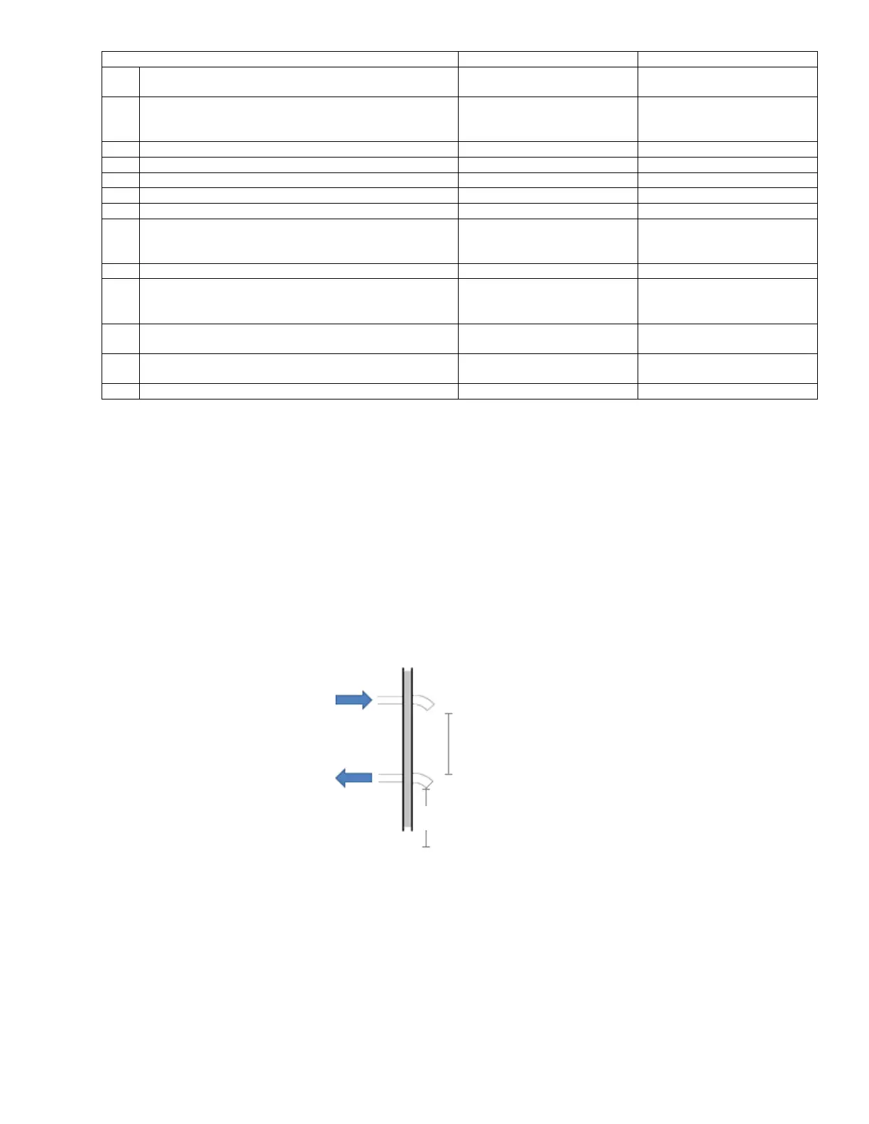
2.4.3 LOCATION OF A SIDEWALL AIR INLET TERMINAL
• The termination point of the sidewall air inlet must be installed a minimum of 3 feet above normal levels of snow accumulation.
• Models 1000 – 1500: The point of termination for the sidewall combustion air inlet terminal MUST be located a minimum 18
inches (45 cm) below the point of flue gas termination (vent cap).
• Models 2000 – 4000: The point of termination for the sidewall combustion air inlet terminal MUST be located a minimum of 36”
(90 cm) below the point of flue gas termination (vent cap).
• The sidewall vent and air termination must be purchased with the boiler to ensure reliable boiler operation.
2.4.4 LENGTH OF AIR INLET PIPE
The maximum total length of the sidewall or vertical roof top combustion air inlet pipe as installed from the appliance to the air inlet
terminal must not exceed 100 equivalent feet (30.5 m) in length. Subtract 7 (2.13 m) to 19 feet (5.8 m) of equivalent length depending on
centerline radius for each 90° elbow installed in the air inlet pipe system. Pressure drop in 45° elbow will be half as much.
18” (45 cm) Minimum
Models 2000-4000:
36” (90 cm) Minimum
Intake