55
PART 8 FIELD STARTUP PROCEDURES
8.1 CHECKING THE INSTALLATION
• Inspect the connections for water, gas and electricity.
• Confirm that water is being pumped toward the heat exchanger inlet (return). Never pump away from the heat exchanger since
this will result in a low-pressure zone, which will allow localized boiling and result in heat exchanger damage.
• Power to the boiler and pump must be from the same circuit to prevent the boiler firing in case the pump is accidentally shut off.
• Vent all air from the heat exchanger prior to firing using the two air vents provided on the heat exchanger. The air vent located
on the outlet of the unit is a manual air vent and the air vent located close to the inlet of the unit is an automatic air vent. Both
air vents can be accessed by removing the top cover and they are located on top portion of the Avenger heat exchanger.
• Inlet gas pressure must be a minimum of 4.0” W.C. for natural gas and 8.0” W.C. for propane.
• With the boiler off, open the main gas supply valve and vent the trapped air from the piping leading to the boiler. Confirm that all
gas connections to the unit are tight and that there are no missing test plugs.
• Connect a manometer to obtain the differential air pressure between negative and positive ports, See Figure 11.
• The air/gas ratio controller automatically adjusts to match the air signal on the gas side. In this way true mass flow control of
air/gas mix is achieved. All boilers are test fired and factory set. A test sheet with actual reading is affixed to the unit.
When venting air from heat exchanger, position the manual air vent tube so that system fluid is directed away from operating personnel.
Always open bleed valve slowly. Some fluid weepage will occur when the valves are opened. Operating personnel must take suitable
measures to protect themselves from exposure to system fluids.
When venting air from heat exchanger, make sure to close the bleed after the air has been removed from the unit. Failure to do
so can cause water leakage, flooding and safety issues.
8.2 CHECKING THE CONSTRUCTION
• Check the boiler wiring to see that it agrees with the wiring diagram supplied.
• Confirm that all terminal strips and field connections are identified.
• Confirm that the Avenger controller is set in the proper mode. Auto reset limits are fixed in all modes.
• With the low-end firing valve in the off position, switch on power to the boiler. The fan motor will accelerate until the Interrupted
Air Switch icon becomes green.
• Once all lights past the STAT are green, the SOLA will try for ignition. When the igniter is hot enough, the gas valve actuator is
energized and if ignition is accomplished the Burner State will show “Run”. If ignition is not accomplished, the Burner State will
show “Safe Startup”. It is normal during initial startup, when air is being purged from the piping, to require two to three tries
before successful ignition.
• With the boiler running, check for flue gas leaks around the flue outlet. Some minor leakage is acceptable.
• Repair any major leaks prior to the next step.
• At the factory adjustments were made to achieve proper input and combustion at maximum and minimum inputs.
8.3 GAS VALVE ADJUSTMENT PROCEDURE
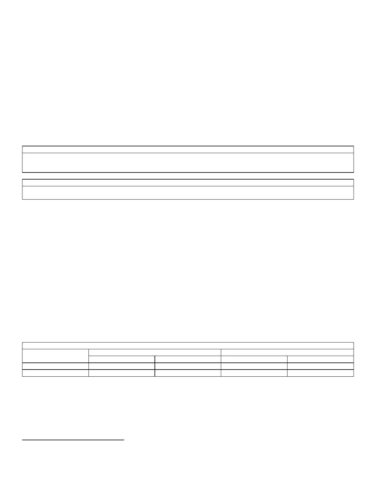
Table 14: Combustion Values
Avenger Combustion Values
If adjustment of the gas valve is required, use the following procedure.
It is imperative that the coldest system water temperature possible is used when setting up low fire combustion. These cold system
temperatures create large amounts of flue condensate resulting in large amounts of condensate build up on the stainless steel heat
transfer tubes. These conditions create the highest back pressure through the boiler and makes for the most critical combustion set up
point when running at low fire. This set up must be achieved quickly to ensure low system temperatures are maintained throughout the
setup of single or multiple boiler installations.
Procedure for Combustion Adjustment
In order to perform adjustments to the gas valve, the Avenger must be firing before proceeding. Light off the boiler and make the initial
adjustment to the Low-End Gas Valve to obtain the specified CO2, CO, at minimum gas input.
 Loading...


