56
Once the interface relay has switched to the High-End Valve, while maintaining the lowest possible water temperature, observe the
differential gas pressure when running with the High-End Valve. The differential gas pressure must not drop below a minimum of 0.25”
W.C. Once the boiler has run for at least 5 minutes with cold water, there should be a maximum amount of condensate in the heat
exchanger. At this point adjust the combustion for CO
2
.
The boiler must continue to run with stable combustion without making any harmonics noise which usually happens from an overly rich
mixture. Once settings are complete at low fire, continue to run the machine for at least 5 more minutes and record the final low fire input
and the combustion data.
To ensure the coldest possible water temperatures for set up on multiple boiler systems, the low fire combustion should be established
on all boilers before setting any boiler high fire combustion rates.
.
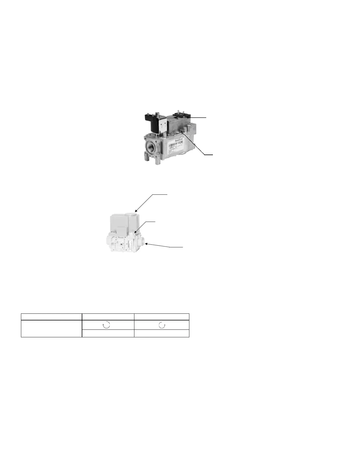
Figure 36: AR1000 Low End Gas Valve
Adjusting the low fire setting of the Low-End Valve
Use the Avenger Control Panel
1. Press [DIAGNOSTICS] button
2. Press [Diagnostic Tests] button
3. Move the firing rate slider to firing rate (%) indicated on test reports.
4. Press [Start Test] to operate the boiler at this firing rate for 5 minutes.
Low Fire Adjustment
After adjusting the screw, wait a moment for the combustion levels to stabilize before attempting to make any further adjustments.
Continue this procedure until combustion levels are satisfied.
When the correct combustion values are achieved replace the screw cap back on to the gas valve.
Adjusting the high fire setting of the Low-End Valve
The high fire setting of the Low-End Gas Valve must be set at a point just before the Siemens gas valve is activated. This will vary from
model to model and the installer will need to monitor at which point on the VFD that the transition occurs. Set the High-End Gas Valve at
2 Hz below where the transition occurs. This transition has been set and tested at the factory and should normally not require adjustment.
Use the Avenger Control Panel
1. Press [DIAGNOSTICS] button
2. Press [Diagnostic Tests] button
Lift top cover to access high fire air/gas ratio
adjustment (use 3mm Allen key for adjustment,
counter-clockwise increases CO
2
)
Low fire air/gas ratio adjustment (use T-40 for
adjustment, clockwise increases CO
2
)
High fire air/gas ratio adjustment
(use slotted screwdriver for
adjustment, counter-clockwise
increases CO
2
)
Figure 37: AR1500 – AR4000 Low End Gas Valve
Low fire air/gas ratio adjustment
(use T-40 for adjustment,
clockwise increases CO
2
)
 Loading...


