51
Wiring the Lead Lag Setup
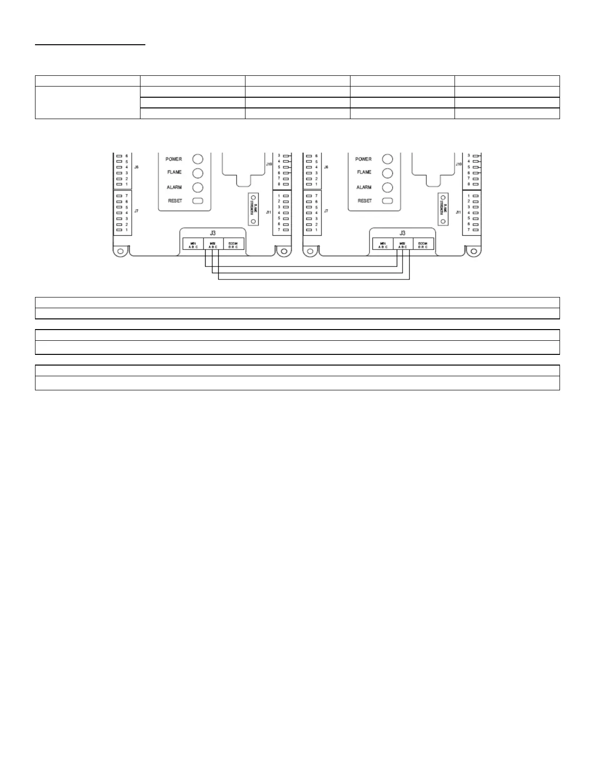
Use Cascade terminals in the juntion box to wire lead lag appliances.
J3, MB2
Figure 31: Lead Lag Wiring Setup (Left: Master, Right: Slave)
Recycle power on all boilers after programming is complete if lag boilers are not discovered automatically
CH Setpoint or DHW Setpoint must match Setpoint located in Lead Lag Master Configuration, for the system to operate correctly.
The Local/Remote switch must be set in the “Local” position on ALL lag boilers.
6.4 LOCAL/REMOTE SWITCH
The local remote switch mounted inside the control box is designed to deliver an enable signal either relying on an external contact
closure (Remote) or enabling the boiler locally (Local). When Remote is selected via the DPDT switch, the Remote Operator contacts
must close to deliver an enable signal. When Local is selected via the DPDT switch, a constant enable signal is present. When
troubleshooting the Avenger, it is recommended to switch to Local mode.
6.5 MODBUS, BACNET IP, BACNET MSTP, LONWORKS, METASYSN2 INTEGRATION
For detailed instructions on interfacing with Modbus/Bacnet/LonWorks/Metasys N2 Network, refer to Camus Hydronics website.