22
3.7.1 REGULATED GAS SUPPLY PRESSURES FOR AVENGER BOILERS & WATER HEATERS
A stable gas supply pressure is important to avoid rough starts with gas appliances such as Avenger boilers and water heaters, which
use a 1:1 ratio control valve for internal gas pressure regulation. Camus requires that all Avenger models be supplied with no more than
14” w.c. supply pressure. This means that lockup pressure must not exceed 14” w.c.
It is paramount that maximum lockup pressure be confirmed before any attempt is made to start up the appliance.
Operating the Avenger at lockup pressures exceeding 14” w.c. is not recommended and could lead to delayed ignitions and damage to
the appliance.
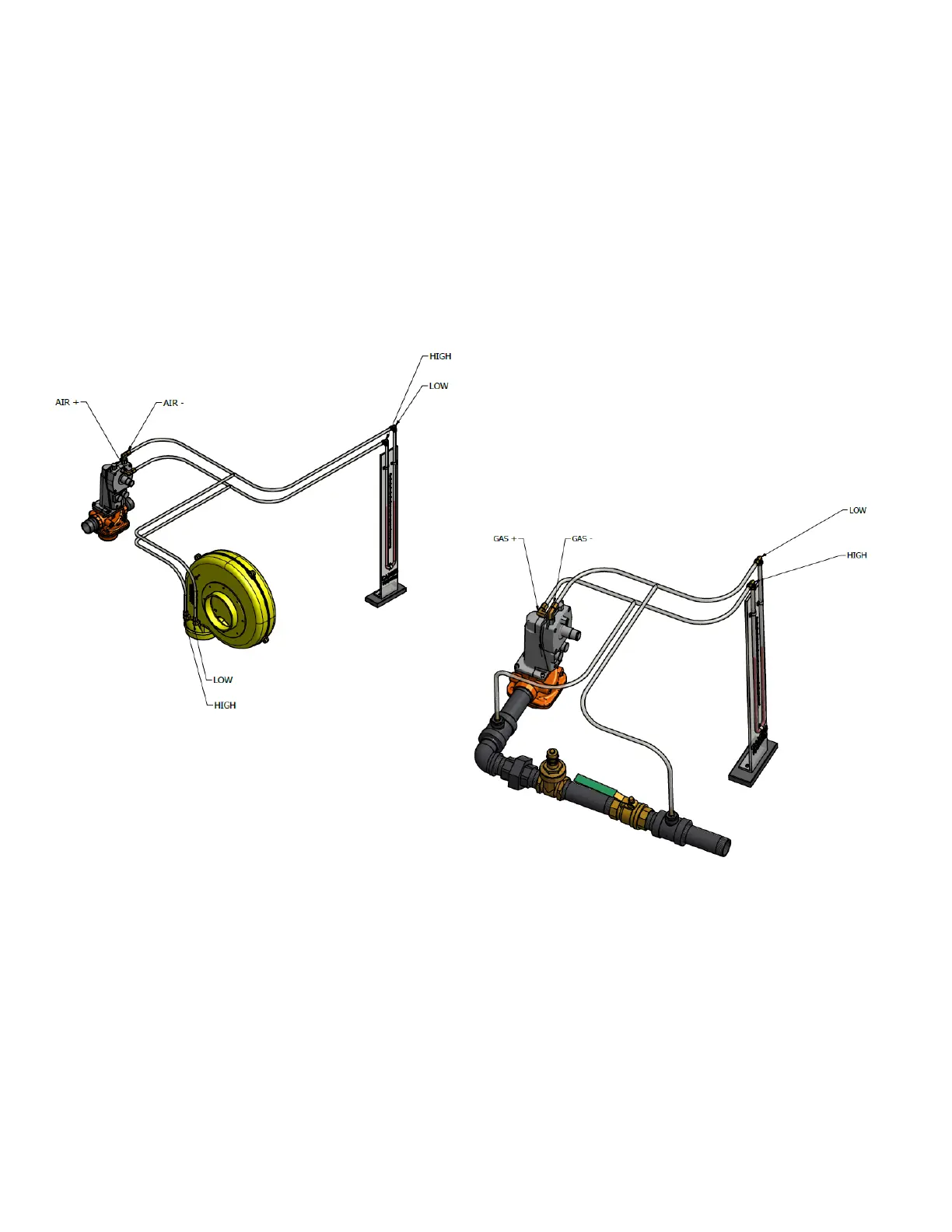
3.8 CHECKING DIFFERENTIAL AIR AND DIFFERENTIAL GAS PRESSURES
Figure 11: Checking Differential Air and Differential Gas Pressures
The 1:1 air/gas ratio control actuator has embossed markings identifying + air, - air, + gas & - gas connections. Using a test hose assembly
fitted with tees, connections can be made from the manometer to the appropriate ports on the actuator:
• Using tees connect a hose from the positive air and the negative air to each of the two sides of a monometer. This will allow the
two pressure points to be measured while at the same time the actuator still receives the proper operating signal.
• If a second manometer is available, it can be connected to the appropriate gas ports. Typically, the gas signal will closely follow
the air signal on all models. If the incoming gas pressure reduces significantly as the VFD accelerates to maximum speed, the
gas signal may lag behind the air signal by up to 15%. This will occur once the actuator has driven downwards as far as it can
go. The amount that the actuator has opened is registered by an indicator arm which is visible through the view window.
• As the appliance comes on and fires, record the maximum inches of water column which is achieved at maximum speed on the
VFD using startup report form. To adjust this differential pressure when commissioning the appliance, use the adjusting screw
on the air shutter to the fan. In all cases, the final adjustment is to be made using a combustion analyzer. Depending on field
conditions differential pressures will have to be adjusted accordingly. Typically, with long lateral runs the differential signal as
read will be reduced from the value shown on the rating plate. The opposite will occur with tall stacks where drafts exceed
negative 0.15” w.c.
• If the appliance will not light off it will be necessary to adjust the low fire as explained in the detailed startup procedure.
Connections for Differential
Air Pressure Measurement
Connections for Differential Gas
Pressure Measurement
(Across the Metering/Trim Valve)

 Loading...


