28
Caution
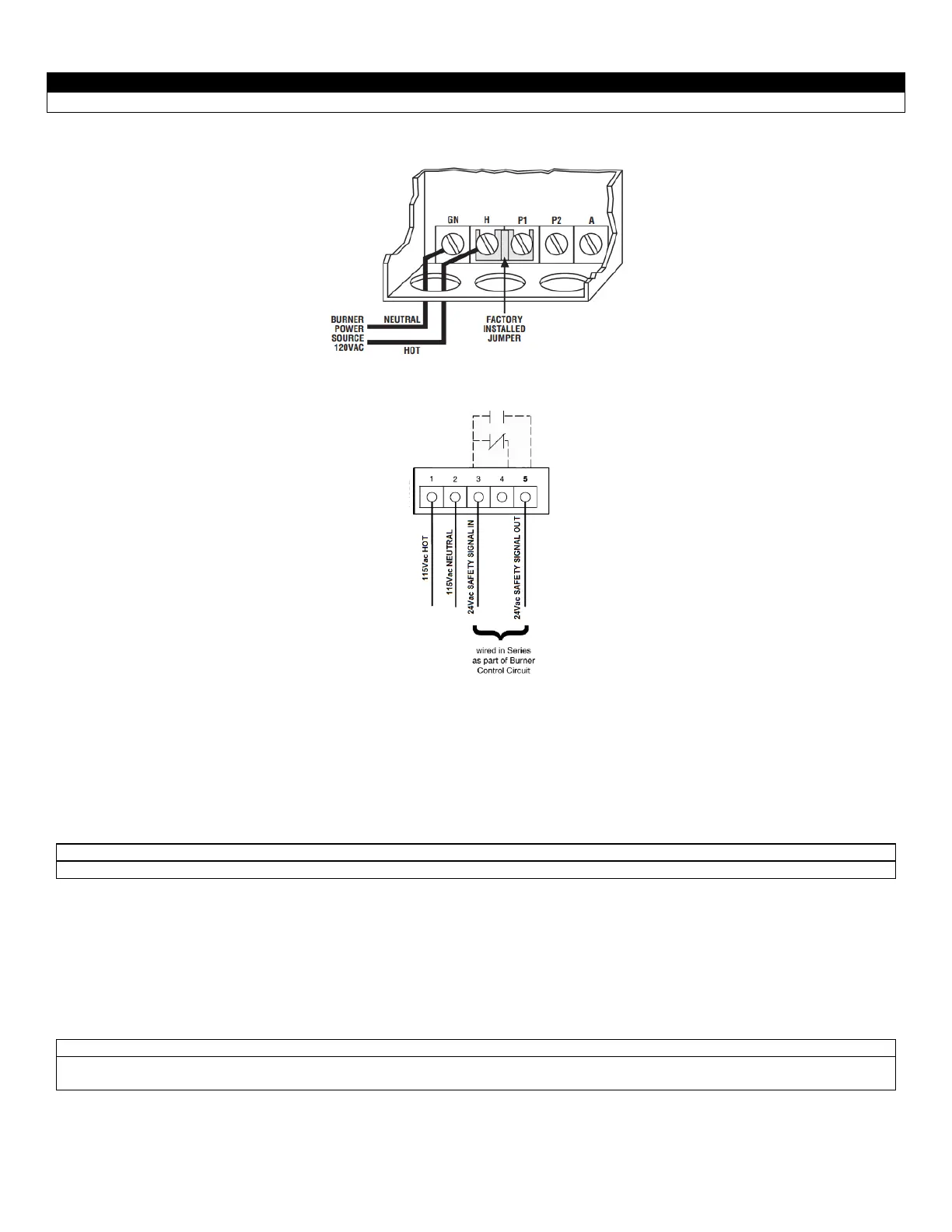
Remove jumper when connecting to 24 VAC circuit.
4.11 RELIEF VALVE
This appliance is supplied with a relief valve sized in accordance with ASME Boiler and Pressure Vessel Code, Section IV (“Heating
Boilers”). The relief valve is to be installed in the vertical position and mounted in the hot water outlet. No valve is to be placed between
the relief valve, and the appliance. To prevent water damage, the discharge from the relief valve shall be piped to a suitable floor drain
for disposal when relief occurs. No reducing couplings or other restrictions shall be installed in the discharge line. The discharge line shall
allow complete drainage of the valve and line. Relief valves should be manually operated at least once a year. If a relief valve discharges
periodically, this may be due to thermal expansion in a closed water supply system. Contact the water supplier or local plumbing inspector
on how to correct this situation. Do not plug the relief valve.
Avoid contact with hot discharge water
4.12 CIRCULATING PUMP SELECTION
The appliance has a stainless steel heat exchanger for fast response and high heat absorption. Selecting the proper pump will ensure
that temperature rise does not exceed the maximum recommended for the application.
4.12.1 CIRCULATING PUMP OPERATION OF HEAT EXCHANGER
This appliance is designed for continuous pump operation when the burner is firing. The pump control option allows the appliance
circulating pump to be cycled “ON” prior to the burner firing and cycled “OFF” sometime after the set point is satisfied.
The operation of the circulating pump is controlled by the Avenger temperature control (SOLA). When the appliance is activated by a
remote operating signal the pump will start and run for the operating cycle and for a post purge period based on temperature difference
between inlet and outlet connections to the appliance. The SOLA can directly operate pumps up to 1/6 HP. Larger pumps will require a
separate relay or contactor.
Connection detail for placing
L.W.C.O in 24V circuit
WARNING: Be sure to remove the
jumper between H and P1
Figure 18: Low Water Cut Off Electrical Connections (Safgard)
Figure 19: Low Water Cut Off Electrical Connections (ITT)