3
increases the modulation signal causes the Low-End Gas Valve to draw more gas. If the Low-End Gas Valve cannot satisfy
demand, at a preset point the staging relay activates the Hot Surface Igniter to provide seamless transition to the High-End
Gas Valve. The fan inlet damper opens and directs power to the High-End Gas Valve while shutting off the Low-End Gas Valve.
As target temperature is approached, the demand signal is reduced and at a pre-set point the hot surface ignitor is activated,
the High-End Gas Valve shuts off and the Low-End Gas Valve is energized. At the same time the fan inlet damper is closed.
As demand continues to decrease the Low-End Gas Valve shuts off and the boiler proceeds to post purge.
b) AR3000 - AR4000 (Proven Pilot): The Avenger controller will activate the Hot Surface Igniter for 22 seconds followed by
energizing the Pilot Valve for 10 seconds, whereupon a signal of 0.8 Vdc must be recognized by the controller at the UV
Scanner to keep the Pilot Valve in an open position. The fan is kept at ignition speed until the stabilization timer is satisfied.
After the stabilization timer expires the Low-End Gas Valve is opened and the Pilot Valve is deactivated. As demand increases,
the modulation signal causes the Low-End Valve to draw more gas and the sequence as detailed in (a) above is followed.
10. If the flame signal is not reached, the module will stop the ignition sequence after the “Main Gas On” period & recycle.
11. The fan speed will slowly decrease as the temperature nears the target. The modulation rate is controlled via a 4-20 mA signal.
If the heat demand is sustained without change, the boiler firing rate will reach a point of steady-state and the fan will rotate at
constant speed.
12. When the heat demand is satisfied or the remote enable is removed, the burner will shut off and the fan speed will ramp up to
the preset Post-Purge speed until the Post-Purge timer is satisfied.
13. The pump continues to circulate until the Post-Purge time is satisfied.
14. The boiler will then go into Standby as it waits for the next heat demand or remote enable.
NOTE
The Hot Surface Igniter is energized with 115V AC when control is switching to/from the High-End Gas Valve to the Low-End Gas
Valve. To avoid shock do not contact bare Ignitor wires at this time
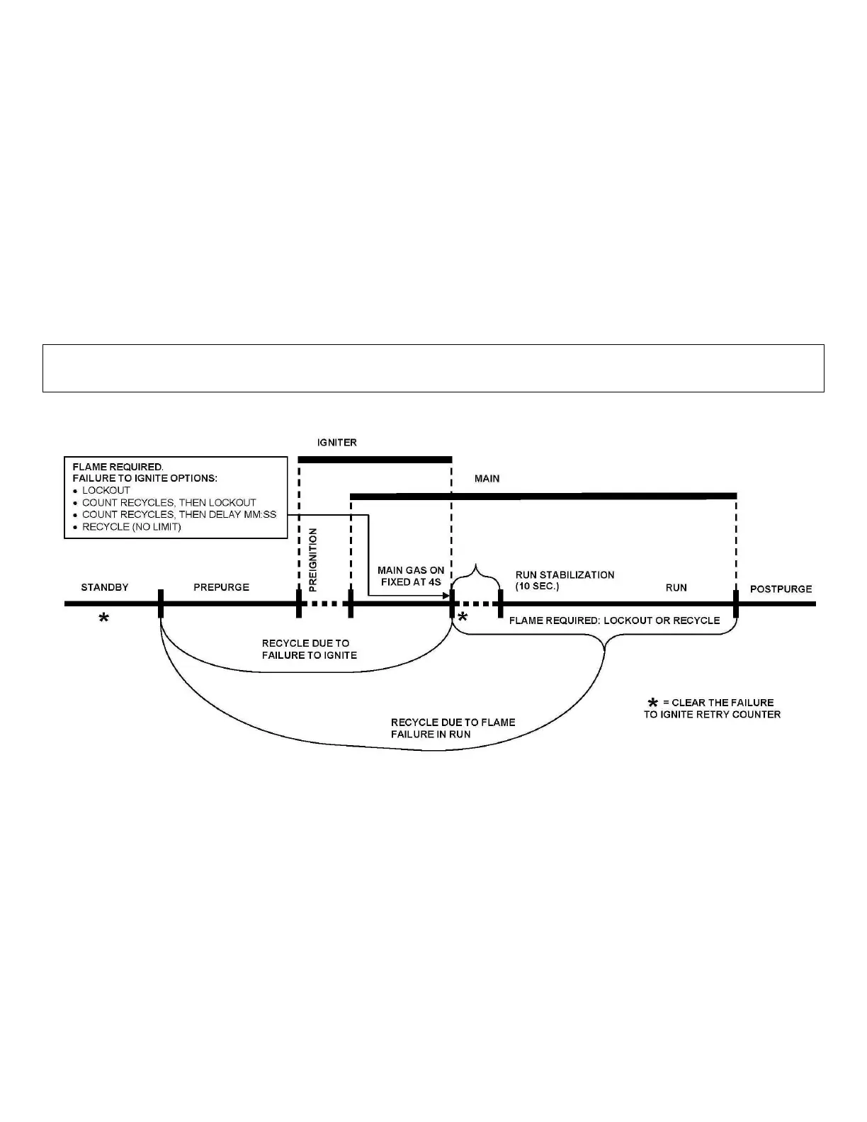
Figure 3: Avenger Ignition Cycle
NOTE:
1. If a flame signal is detected at the end of the Pre-Purge period, an error will occur.
2. If at the end of the safety period (4 sec) no flame is detected, the control will go to Post-Purge to remove the unburned gas.
After this, a re-ignition attempt is started following the same cycle. The number of re-ignition attempts is limited to 2 after which
a lockout occurs.
3. The burner can only be ON continuously for a period of 24 hours. After this, the burner is switched OFF and a restart sequence
follows.
4. The Hot Surface Igniter is de-energized at the end of the ignition period to allow for ionization detection.
1.4.1 HEAT TRANSFER PROCESS
1. Burner input rate continues to increase until water temperature reaches the set point temperature.
2. Burner input rate may stabilize at a fixed rate when demand equals input.
3. Burner input rate will decrease when water temperate approaches temperature set point.