50
6.2.6 SENSOR CONFIGURATION
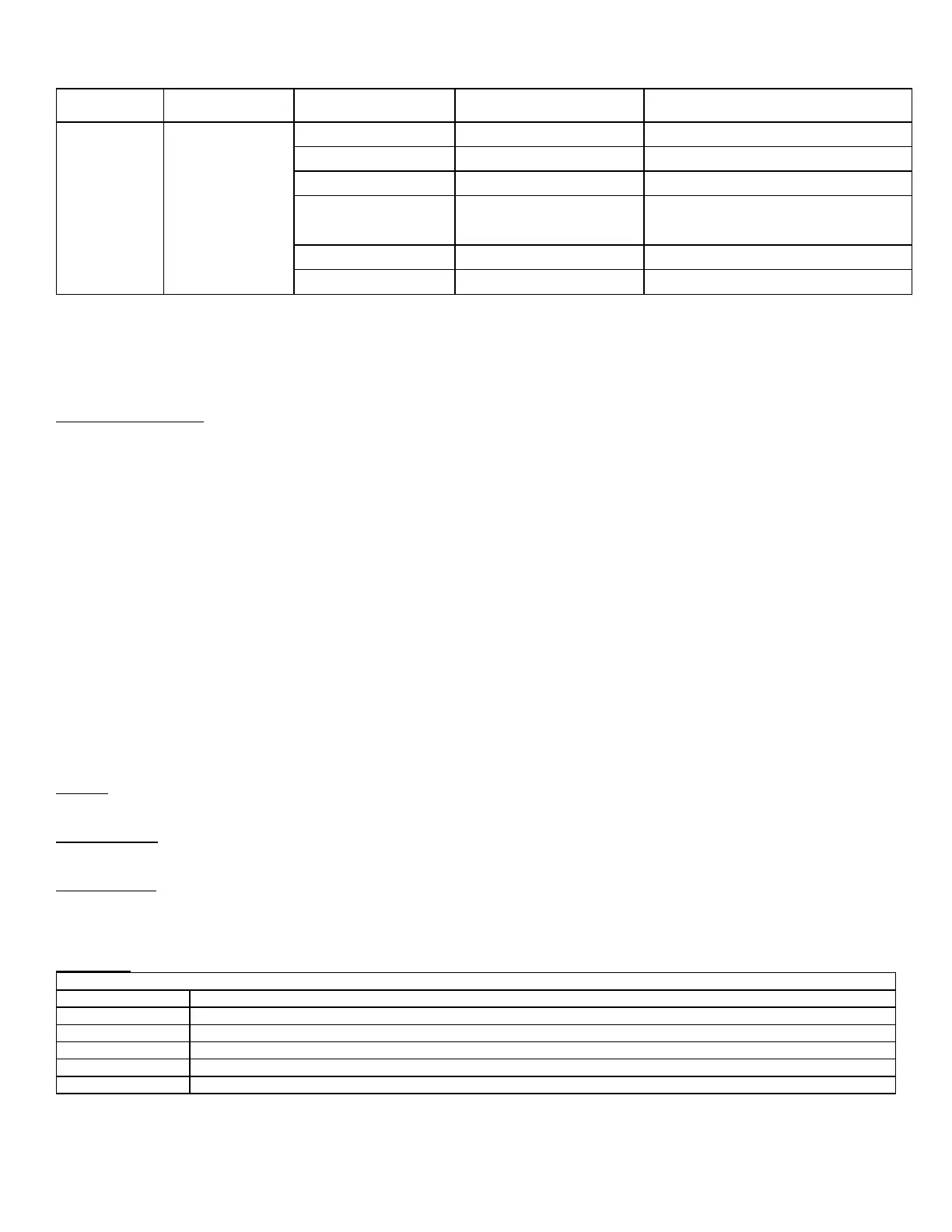
Parameter Selection Description
Sensor
Configuration
S1 (J8-4) sensor
10K NTC single non-safety
Inlet Sensor
S2 (J8-6) sensor 4-20mA 4-20mA Input Signal
S3S4 (J8-8, 10) sensor 10K NTC dual safety Outlet Sensor
S5 (J8-11) sensor 10K NTC single non-safety
Outdoor Sensor: Standalone boiler or
Slave boiler
Header sensor: Master boiler
S6S7 (J9-1,3) sensor 10K NTC single non-safety DHW Sensor (ARW Only)
S8S9 (J9-4,6) sensor 10K NTC single non-safety Stack Sensor
6.3 LEAD LAG SETUP
All SOLA controllers are programmed with a default adress of 1. The address of the slave controllers in the system must have a unique
address (1..8).
Sequence of Operation:
When a boiler is set as Lead Lag Master = Enabled and Modbus address =1, the controller of this boiler will drive the lead lag operation.
The outdoor temperature sensor connected to the slave boiler 2 (ie. B-2) will be the outdoor sensor for the lead lag system.
• The system temperature sensor connected to boiler 1 (the master) in terminals labeled “Outdr/Sys” in the junction box will be
the control sensor for lead lag operaiton.
• The start/stop signal connected to boiler 1 (the master) at terminals labeled “Remote Operator” will be the enable signal for lead
lag operation.
When the enable signal is present and there is a heat demand, the lead boiler will start and uses the lead lag parameters for boiler
modulation. After a period of “Interstage delay” the master boiler compares the lead lag temperature with the lead lag set point and will
check if:
1. An additional boiler is needed: Lead lag temperature < Lead lag setpoint – Add stage Error Threshold
2. Number of boilers remain the same: Lead lag temperature > Lead lag setpoint – Add Stage Error Threshold AND Lead lag <
Lead lag setpoint + Drop Stage Error Threshold
3. A boiler should stop: Lead lag temperature > Lead lag setpoint + Drop Stage Error Threshold
4. All boilers off: Lead lag temperautre > Lead lag setpoint + Off Hysteresis
If the lead lag master system is interrupted, the remaining boilers will operate as standalone boilers based on the Central Heat or DHW
parameters when set to “Enabled”.
Rotation
Rotation time is configurable based on equalized run time (default) or a fixed rotation schedule.
Interstage Delay
The length of time to wait between requesting a slave SOLA to fire. (Default: 2 minutes)
Base Load Rate
When a call for heat is initiated the lead boiler runs up to the desired base load rate (default: 80%) and continues to operate in this fashion
based on the above 4 scenarios. If the lead lag temperature is not satisfied a second boiler is fired and they would both operate up to
80% fire rate.
Slave State
Table entry is unused or empty
Slave is operational and ready to use
Stage is getting ready to fire
Stage was getting ready but is not needed
Slave is locked out or disabled
Slave is in time delay to verify that it is operational before considered to be available