24
3.10 VENTING OF GAS VALVES AND PRESSURE SWITCHES
The optional gas pressure switches may be provided with threaded termination points to be vented to the atmosphere, outside the building.
The gas pressure regulation function is provided by the ratio gas valve which does not require installation of a vent line. The optional gas
pressure switches are installed in the upper chamber of the appliance. Threaded vent line connections from components requiring an
external vent line are provided on the component. These vent line connection points may be accessed by removing the top of the
appliance. Local codes may require the routing of these bleeds and vents to the atmosphere, outside the building. Proper routing of vent
lines to the atmosphere from the factory supplied termination points is the responsibility of the installing contractor.
3.11 BURNER
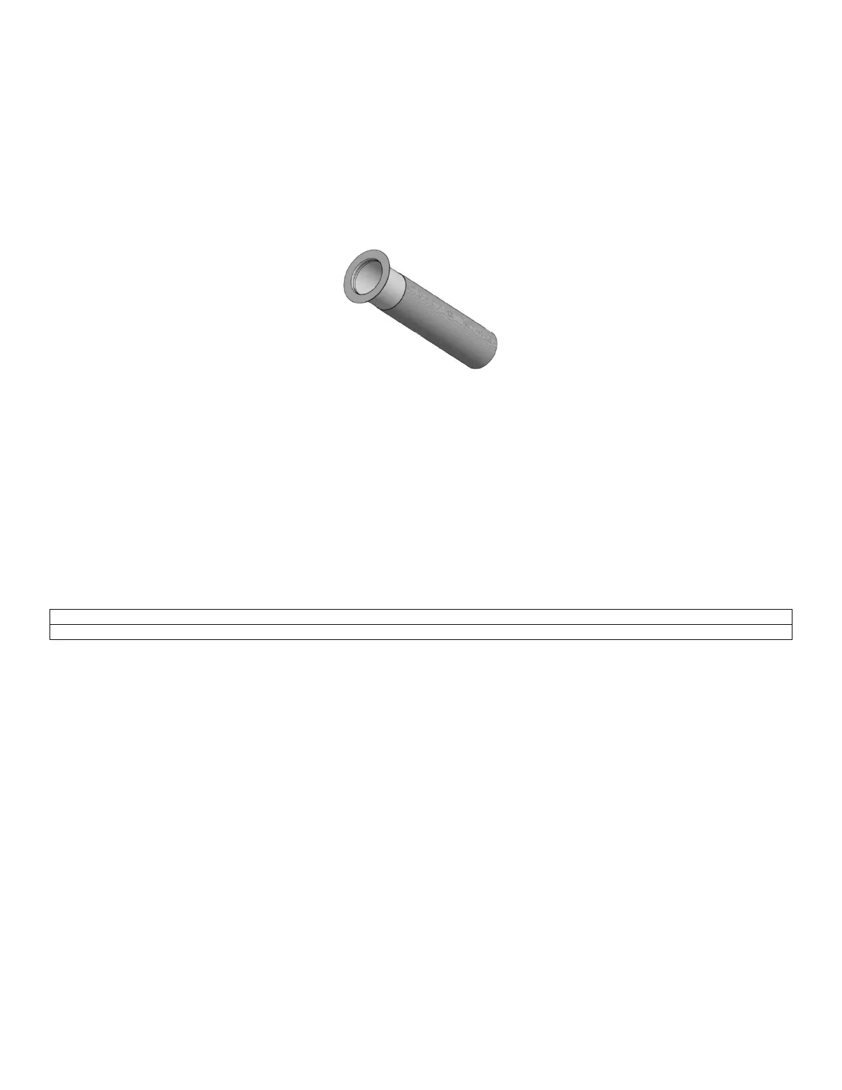
Figure 14: Burner
This appliance uses a single cylindrical burner installed vertically into the opening located in the center of the heat exchanger. The burner
consists of a round mounting flange welded to a mixing tube. The top side of the mixing tube provides the transition which mounts the
discharge from the combustion air fan into the burner. The bottom side of the mixing tube is attached to a stainless steel perforated
sleeve. This stainless steel sleeve is covered with a metal fiber alloy material that forms the burner port surface. The burner port material
is a metal fiber material which is a unique alloy of iron, chrome, aluminum and several rare earth metals. This alloy is designed to operate
stress free as a burner port surface. The burner port surface can sustain operation from a blue flame down to infrared conditions as the
burner input varies. Infrared operation will occur only as turndown is increased.
Model 1000-2500: Utilizes direct ignition. The burner mounting flange provides a flame view port and the mounting point for the Hot
Surface Igniter and the UV Scanner.
Model 3000-4000: Utilizes proven pilot ignition. The burner mounting flange provides a flame view port, the mounting point for the Hot
Surface Igniter, a connection to the pilot tube and the UV Scanner.
The Hot Surface Igniter and UV Scanner are removable from the burner mounting flange without removing the burner assembly from the
heat exchanger.
Never use an open flame (match, lighter, etc.) to check gas connections, use a soap solution instead.

 Loading...


