25
PART 4 WATER CONNECTION
• Check all applicable local heating, plumbing and building safety codes before proceeding.
• If the appliance is installed above radiation level, it must be provided with a low water cut-off (LWCO) device at the time of
appliance installation (available from factory). Some local codes require the installation of a low water cut off on all systems.
• A pressure relief valve is supplied with each Avenger model. The relief valve must be mounted in a vertical position and piped
to the floor in a manner acceptable to the enforcing authority.
• Minimum operating system water pressure should not drop below 12 PSIG. A minimum water pressure relief valve setting
of 50 PSIG is recommended.
• Be sure to provide unions and gate valves at inlet and outlet to the appliance so that it can be easily isolated for service. The
provision of a flow setter valve at the appliance outlet will facilitate setting of the proper flow at the desired temperature rise at
high fire.
• Special attention to minimum water flow rates will ensure that temperature rise is not excessive. See Table 8.
• To eliminate trapped air, install venting devices at high points in the system as well as in the piping on the suction of the pump
and in the piping on the discharge of the appliance.
• Use suitable pipe hangers or floor stands to support the weight of all water and gas piping.
• Always pump toward the heat exchanger inlet. Never pump away from the exchanger since this will result in a low-pressure
zone, which will allow localized boiling and result in heat exchanger damage.
• The Avenger must be installed so that the gas ignition system components are protected from water (dripping, spraying, rain,
etc.) during appliance operation and service (circulator replacement, control replacement, etc.)
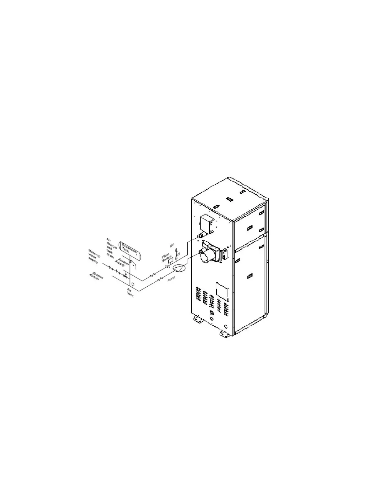
Figure 15: Typical Space Heating System
4.1 FREEZE PROTECTION
• Appliance installations are not recommended outdoors in areas where danger of freezing exists unless precautions are taken
(outdoor models only). Maintaining a proper mixture of water and propylene glycol is the preferred method of freeze protection
in hydronic systems. This mixture will protect the appliance to approximately -35ºF (-37ºC). To maintain the same temperature
rise across the appliance increase the GPM flow by 15% and the head loss by 20%.
The following example demonstrates the procedure to follow for calculating the revised head for the heat exchanger when using a
water/glycol mixture.
• Given that Camus is showing a heat exchanger flow and head loss of 100 gpm @ 10 feet
• Increasing the flow by 15% now results in a head loss of 13 feet at 115 gpm (from B&G system syzer). At this increased flow
Camus now recommends increasing the head loss by 20%.