20
Table 7: Gas Pressures at Inlet to Appliance
*12.0 IN.W.C. for ARP-4000
The gas supply line must be of adequate size to prevent undue pressure drop and must never be smaller than the size of the connection
on the appliance. Sizing based on Table 6 is recommended.
Before operating the appliance, the complete gas train and all connections must be tested using soap solution.
Verify that the appliance is supplied with the type of gas specified on the rating plate. Heating values of local natural gas are to be between
950 and 1010 Btu/ft
3
. Consult factory if heating values are outside this range or if a gas with a mixture of constituents is being used.
3.4 AIR/GAS RATIO VALVE
Avenger models utilize a dual seat negative pressure air/gas ratio control valve at the low end and an air/gas ratio control valve at the
high end. This combination allows the Low-End Valve to fire down to the minimum input with high turn down ratio. At a pre-determined
point, control is passed from the Low-End Valve to the High-End Valve and at the same time the fan air Inlet Damper is gradually opened.
The High-End Valve controls the pressure difference across a flow orifice in the manifold supply line as a function of the pressure
difference across the combustion air supply to the burner. The High-End Valve actuator maintains a matching 1:1 air to gas ratio as the
volume of air changes based on the operation of the combustion air fan.
The air/gas ratio of both Low-End Valve and High-End Valve are preset at the factory and adjustment is not usually required if gas supply
pressure is maintained within the specified range.
A reduction of up to 30% is permitted in the inlet gas pressure between light off and full fire conditions.
If the manifold differential pressure is to be measured, refer to section 3.8 Checking Differential Air and Gas Pressures for Proper
Measurement.
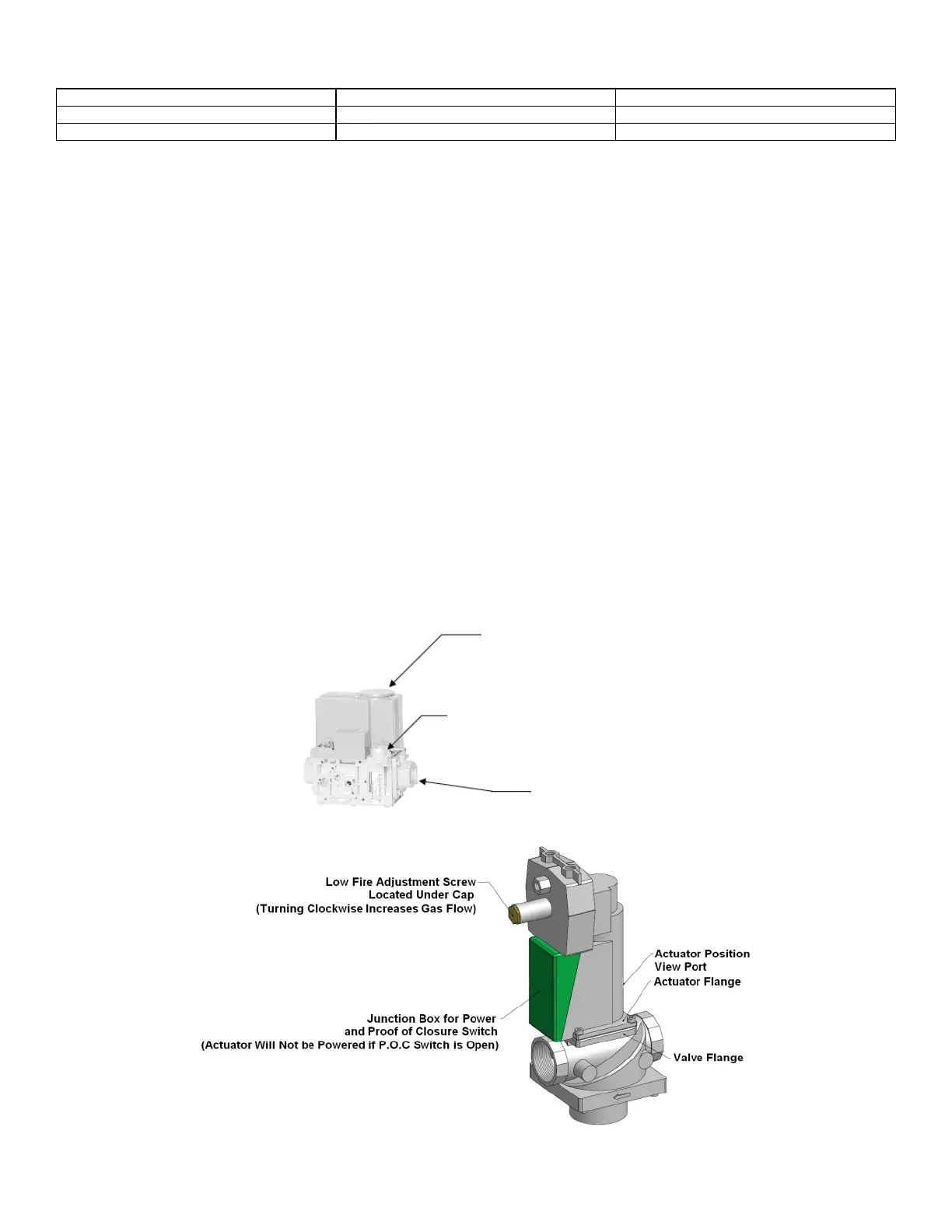
Figure 10: 1:1 Differential Air/Gas Ratio Control Valve
Lift top cover to access. High fire air/gas ratio adjustment
(Use 3mm Allen key for adjustment, counter-clockwise increases CO
2
)
Low fire air/gas ratio adjustment
(Use T-40 for adjustment, clockwise increases CO
2
)
Figure 9: 1:1 Negative Pressure Control Valve
 Loading...


