63
Table 17: Alert Codes
LCI off, safety circuit is open
Setpoint was overridden due to sensor fault
Modulation was overridden due to sensor fault
Delta-T limit exceeded (70ºF)
Ignition failure occurred
Modulation rate was Limited due to outlet limit
Modulation rate was Limited due to Delta-T limit
No Lead Lag slaves available to service demand
Using backup Lead Lag header sensor due to sensor failure
Lead lag slave communication timeout.
LCI off, safety circuit is open
Demand off during measured purge time
Abnormal Recycle: Flame was not on at end of Ignition period
Abnormal Recycle: Flame was lost during Main Flame Establishing Period
Abnormal Recycle: Flame was lost early in Run
Abnormal Recycle: Flame was lost during Run
Interlock Off, safety circuit is open
Hardware flame bias. Flame sensor wire needs to be re-routed.
Delta T inlet/outlet limit was exceeded
Lead boiler was rotated due to measured run time
+
The alarm LED and alarm contacts are closed and will remain closed until the ‘RESET’ button is pressed.
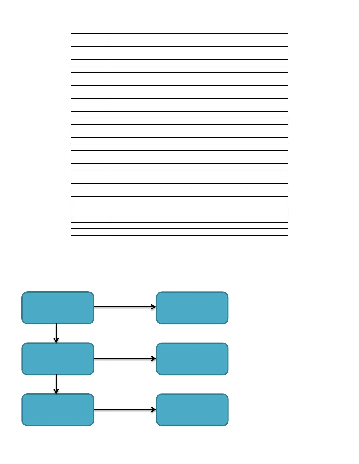
Alert 291: Abnormal Recycle: Flame was not ON at the end of ignition
Alert 294: Abnormal Recycle: Flame was lost during Run
Alert 324: Abnormal Recycle: Hardware flame bias
Alert 377: Abnormal Recycle: Hardware flame bias delta
These errors occur when a flame signal is not detected by the UV Scanner. A minimum signal of 0.8Vdc must be detected by the UV
Scanner to prove the flame.
For High-End Valve, staging relay switch over is factory set and normally does not require field adjustment.
Check UV Scanner wire
Move UV Scanner wire
away from harness
bundle
Check hot surface igniter
for minimum 3.0A
reading
Replace igniter
Check UV Scanner
viewing window for
carbon deposit
Clean and/or replace
Separated from
harness bundle
 Loading...


