7
ENG
“Ultrasound for fancoil” +0300059IE - rel. 1.7 - 24.10.2022
3. GENERAL DESCRIPTION
3.1 humiSonic
Ultrasound humidiers can be used for vast variety of applications, e.g.
data centers, climate rooms, close control units and food preservation,
for the RH% control. It is a device developed to be integrated into fan or
fancoils, but can also be used in other applications.
Atomised water production of the units is respectively is 0.5 l/h (UU01F)
and 1 l/h (UU01G), delivered directly into the air stream.
3.2 Name/part numbers
Code Description
UU01FD Compact ultrasonic humidier, 0.5 l/h, 230V - 1~
UU01F1 Compact ultrasonic humidier, 0.5 l/h, 115V - 1~
UU01GD Compact ultrasonic humidier, 1 l/h, 230V - 1~
UU01G1 Compact ultrasonic humidier, 1 l/h, 115V - 1~
Tab. 3.a
3.3 Dimensions and weights
Model with 1 piezoelectric
transducer
Model with 2 piezoelectric
transducers
A
Fig. 3.a
UU01F UU01G
dim. mm (“) A 121 (4,76) 185 (7,28)
B 125 (4,92) 125 (4,92)
C 221 (8,70) 216 (8,50)
weights kg (lb) packaged 3,9 (8,60) 5,5 (12,13)
empty 2,8 (6,17) 4,4 (9,7)
Tab. 3.b
3.4 Opening the packaging
NOTICE: dropping or bumping the humidier may irreparably damage
its internal components.
□ Make sure the package is intact upon delivery and immediately notify
the transporter, in writing, of any damage that may be due to careless
or improper transport;
□ move the humidier to the site of installation before removing from
the packaging, grasping the neck from underneath;
□ open the cardboard box, remove the protective material and remove
the humidier;
□ the unit must always be stored in a dry place before installation.
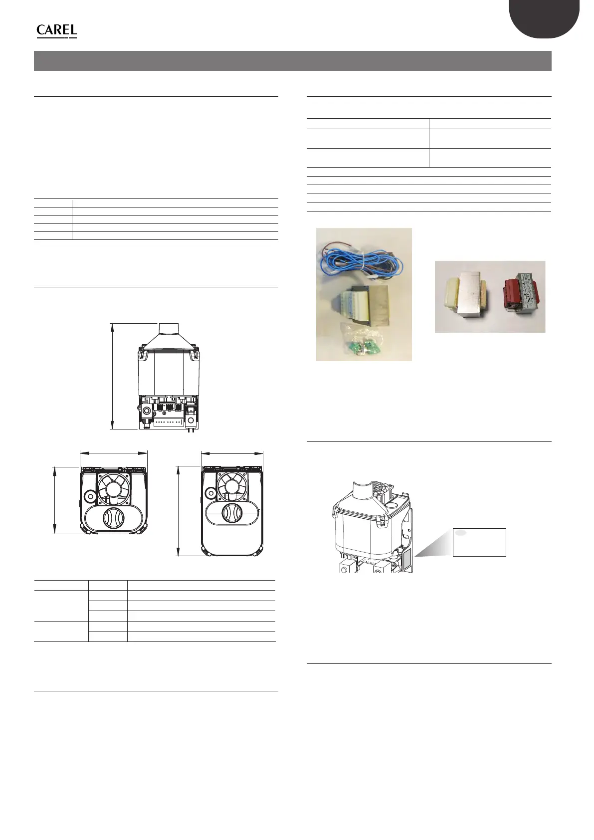
3.5 Material supplied
Check that the following are present:
Model
230 V 115 V
1 transformer: 230 V primary and
dual secondary, 50 V and 24 V
1 transformer: 115 V primary and
50 V secondary
-
1 transformer: 115 V primary and
24 V secondary
Wiring
2 screws
Electrical connectors
L tting (water supply inlet)
User manual
Fig. 3.b
Fig. 3.c
NOTICE: on the 230 V model, a pair of wires marked L and N remain
unused.
3.6 Identication label
The humidiers can be identied by the packaging label and the
identication label.
Rev. 2.0
S.N.
A00005***
Date
15-Jan-2019
Code
UU01
****
Fig. 3.d
NOTICE: tampering, removal or absence of the identication label or
anything else that does not allow certain identication of the product
will make any installation or maintenance operations dicult.
3.7 Positioning
• The humidier may only be accessed by specialist personnel;
• make sure the humidier is level horizontally, observing the minimum
clearance of 200mm on the sides to leave room for maintenance;
• position the humidier so as to allow the atomised water to be freely
delivered and the water freely drained;
• position the transformer in a place that’s protected against possible
water leaks and in any case not underneath the humidier.