13
ENG
“Ultrasound for fancoil” +0300059IE - rel. 1.7 - 24.10.2022
6.4 Dipswitch conguration:
2
3
64
7
5
1
8
ON
Fig. 6.d
1. Communication
OFF Serial 485 Carel/Modbus
ON tLAN
2-3 tLAN address (if 1 is ON)
OFF/OFF - -
OFF/ON address 1
ON/OFF address 2
ON/ON address 3
4 Serial 485 / tLAN baud rate
OFF 19200
ON 9600
5-6 Humidity set point
OFF/OFF 50 %rH
OFF/ON 30 %rH
ON/OFF 40 %rH
ON/ON 60 %rH
7 TAM
OFF disabled
ON enabled
8 Production transducer management (only for 2-transducer version)
OFF --> parallel management (modulation of all 2)
ON --> if demand is less than 50%, it works only one transducer at a
time, alternately
Tab. 6.c
6.5 Main board connections
Depending on the type of signal used, atomized water production can be
enabled and/or managed in dierent ways.
HUMIDOSTAT OR REMOTE CONTACT (ON/OFF action)
Production is enabled by closing terminal M14.
M14 can be connected to a switch, a humidistat or a controller (voltage-
free contact, max 5 Vdc open, max 7 mA closed).
TH TEMPERATURE/HUMIDITY PROBE (Optional)
If the TH TEMPERATURE/HUMIDITY PROBE is connected to the G termina,
atomized water production starts if:
• the terminal M14 is closed;
• in humidity control mode (A0 = 3), The humidity value measured by
the probe is lower than the set point (pre-set at 50% rH and modiable
via dipswitches 5-6 or on the display);
• in dew point temperature control mode (A0 = 4), the dew point value
calculated based on the temperature and humidity measured by the
probe is lower than the set point (pre-set at 10°C/50°F and modiable
via the optional display).
Remote
ON/OFF
M 14
+ GND
Fig. 6.e
485 SERIAL CONNECTION
Carel/Modbus protocol
RS 485
RX+/TX+
GND
M 11
RX-/TX-
Fig. 6.f
NOTICE: for RS485 connections in household (IEC EN 55014-1) and
residential (IEC EN 61000-6-3) environments, use shielded cable (with
shield connected to PE both on the terminal and controller ends),
maximum length specied by the EIA RS485 protocol, equivalent to
European standard CCITT V11, using AWG26 twisted pair cable; the input
impedance of the 485 stage is 1/8 unit-load (96 kOhm).
This conguration allows a maximum of 256 devices to be connected,
with cables in separate conduits from the power cable.
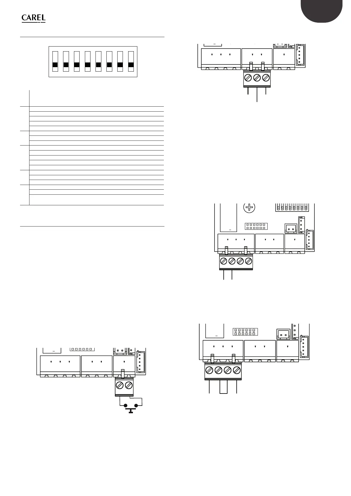
ALARM RELAY
This is used to signal one or more alarms via a remote connection.
Alarm relay
NO
COMMON
M 15
Fig. 6.g
ALARM RELAY POWER SUPPLY
The connections shown in gure can be used to directly control a light or
an auxiliary relay coil 30 Vdc (24 Vac rectied), 3 W max.
+24 V
GND
Alarm signal
(max 3W)
M 15
Fig. 6.h
NOTICE: in industrial environments (IEC EN61000-6-2) the signal cables
leaving the unit must not exceed 10 m (33 ft)
(1)
in length: remote on/
o digital input (terminals M14.1...M14.2) and shielded cable for RS485
communication.