33
ENG
“Ultrasound for fancoil” +0300059IE - rel. 1.7 - 24.10.2022
16. NETWORK CONNECTION
16.1 Settings
The Main unit can control the operation of up to 3 Secondary units
connected via tLAN network. For the electrical connections see the
wiring diagram on the next page. Dipswitches 1-3 on the Main unit must
all be set to OFF. Each Secondary unit must be suitably congured using
the dipswitches, as follows:
1: Set ON for serial port (M11) conversion from RS485 to tLAN;
2/3: Secondary address, as in the gure below.
16.2 Control logic
The Main unit controls each connected Secondary unit via the following
parameters:
• enable/disable operation;
• level of atomised water production.
The control signals (probe/humidistat/external controller) are only read
and managed by the Main unit, which then controls operation of the
Secondarys. The level of production on the Main unit is sent to all the
Secondarys:
Ex.1: Main congured for proportional control (see chap. “Electrical
connections”) and request at 90%: the Main and each Secondary will
modulate at 90% capacity (see chap. “Operating principles”).
Ex.2: Main congured for control by room probe, set point 50 %rH: when
reaching the set point, the Main and all the Secondarys will stop atomised
water production.
Each unit (Main or Secondary) is independent as regards the atomised
water production control logic and all the other functions.
16.3 Management of Secondarys from
terminal (Main)
From the main screen press PRG for 3 seconds and enter the password:
90. The terminal will display the status of the Secondary connected, with
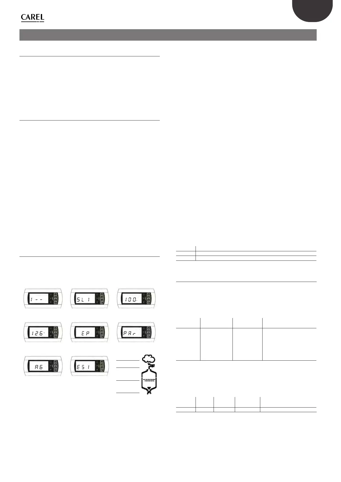
the following logic - starting from the digit on the left:
Unit 1, Unit 2, Unit 3.
Fig. 1 Fig. 2 Fig. 3
Fig. 4 Fig. 5 Fig. 6
Production
Fill
Water presence
Drain
Fig. 7 Fig. 8
Fig. 9
The symbol 1 means “unit online”, while the symbol
means “unit oine”.
Fig.1
shows an example of Unit 1 online (left digit 1) while Unit 2 and 3
oine (central and right digit
).
Press ENTER on the terminal opens the menu for selecting the unit to be
controlled, using UP and DOWN to select the desired unit.
Fig.2
shows
the screen for selecting Unit 1.
Pressing ENTER accesses the menu for controlling the desired unit, UP
and DOWN scroll the following elds:
• Percentage request sent to the Main
(Fig.3)
.
• Operating hour counter
(Fig.4)
, resettable pressing UP+DOWN for 5
seconds (see “parameter d3”).
• Unit alarms (
Fig.5
, -- means no alarms are present), resettable pressing
UP+DOWN for 5 seconds.
• humidier status (Enb = enabled): pressing ENTER disables the
humidier and dIS is shown on the main screen; to enable the unit
press ENTER again;
• limit probe set point and proportional band (SL, bL), if enabled by
setting bH=1, parameter bH available in the list of parameters Par
• Access parameter conguration menu
(Fig.6)
.
The icons, in this display, indicate the status of the selected Secondary
(Fig.9)
Pressing ENTER from parameter conguration menu access screen opens
the list of parameters that can be set
(Fig.7)
.
For the meaning of the parameters see Conguration parameters.
Parameter b8 is used as a timeout for recognising when a unit is oine;
depending on the number of secondarys connected, it may be necessary
to change this parameter, set by default to 10 s.
Alarms
From the main screen the Main displays any alarms present on a certain
secondary with the code ESX, where X is the address of the secondary
with the active alarm (Fig. 8, Secondary 1 alarm).
For details of the current alarm access the menu for the secondary in
question. Each unit is independent in managing its own alarms, except
for those relating to the control signals connected to the Main, which
aect the entire network of humidiers.
Alarm Description
PU External control signal not connected
OFL Supervisor disconnected and Main in request from serial mode
Tab. 16.a
16.4 Control via supervisor (Carel/Modbus®)
Supervisor variables I62 and I63 (Modbus® 189 and 190) can be used to
display and set the secondary parameters. Variable I62 (Modbus 189)
must be written as shown in table. To read the variable, the value will be
saved for variable I63 (Modbus 190) after writing I62, while to write the
variable, the value written will then be available for variable I63.
Bit 15 Mode Bit 13-14 Secon-
dary address
Bit 8-12
Variable type
Bit 0-7
CAREL supervisor address
0=Read
1=Write
01 = Seconda-
ry 1
10 = Seconda-
ry 2
11 = Seconda-
ry 3
00100=Int.
01000=Analog
10000=Dig
E.g.: 0000 1000=8
Tab. 16.b
E.g.: write parameter P0 for Secondary 2 to 70
• Write I63 to 70
• Write I62 to 50224
Write Secon-
dary 2
Integer
variable
P0=
address 48
1 10 00100 00110000 =1100010000110000=50224