20
ENG
“Ultrasound for fancoil” +0300059IE - rel. 1.7 - 24.10.2022
10. CONFIGURATION PARAMETERS
To access and set the following parameters, see chapters 8 and 11.
10.1 Basic parameters
Parameter UM range def note
A0 Operating mode
0 = On/O mode from auxiliary card probe input
1 = Proportional mode from auxiliary probe input
2 = Humidity probe mode from auxiliary card probe input
3 = if the temperature and humidity probe TH is present, the humidity is read and adjusted; otherwise On/
O mode from contact on main board. Parameter A2 is not used.
4 = Dew point control mode by reading the temperature and humidity probe TH
- 0...4 3
A1 Unit of measure 0 = International system; 1 = Imperial system - 0...1 0
A2 Type of external sensor (optional card) (0 = On/O ; 1 = 0-10V; 2 = 2-10V; 3 = 0-20 mA; 4 = 4-20 mA) - 0...4 1
P0 Maximum production % Pn...100 100
P1 Proportional control hysteresis for mode A0=1 % 2...20 2
Pn Produzione minima % 5...P0 10
SP Humidity Setpoint / dew point temperature
(1)
%rH 20...95 50 only if terminal connected, other-
wise values set by dipswitch
°C
(°F)
-16…35
(3…95)
10
(50)
only editable on the terminal
SL Humidity limit set point / dew point temperature %rH 0…100 70
°C
(°F)
-16…35
(3…95)
15
(59)
bP Proportional band for control with probe %rH 2…20 10
°C
(°F)
1…10
(2…20)
3
(5)
bL Proportional band for humidity / dew point temperature limit %rH 2…20 10
°C
(°F)
1…10
(2…20)
3
(5)
C0 Default display (Terminal)
0 = Probe reading/control signal; 1 = Hour counter
- 0...1 0
Tab. 10.a
10.2 Advanced parameters
Parameter UM range def note
A3 Probe minimum %rH 0…100 0
A4 Probe maximum %rH 0…100 100
A5 Probe oset %rH -99…100 0
A6 Duration of fan active with production in standby for tank drying min 0…15 5
A7 Fan speed % 40…100 100
A8 Maximum evaporation time for reduced production alarm min 0…200 30
A9 Minimum evaporation time for discharge leakage management min 0…A8 0
AA Waiting time for retry min 1…60 10
Ab Percentage of A8 to carry out level test % 50…90 70
AC Maximum time for active transducers during loading, with water below high level s 1…60 10
Ad Water permanence time above high level causing new drain for level sensor test s 1…60 10
AE Restart fan time in standby for TH probe reading min 0…120 0
AF Piezoelectric transducer working life h 0...9999 9999 with demineralised water
b0 Operating options (see table for parameter b0) - 0…255 7
b1 Time between two washing cycles min/h 0…120 60
b2 Inactivity time for washing h 1…240 24
b3 Washing time: duration of the loading and unloading phases active at the same time min 0…10 1
b4 Start delay time s 0…120 10
b5 Operating hours for CL alarm h 0…9999(*) 5000
b6 Time to display new CL alarm after reset from keypad (without resetting hour counter) min 0…240 60
b7 Transducer modulating control period s 0…10 1
b8 Probe disconnected delay s 0…200 10
b9 OFF delay from TAM s 0…60 2
bA Maximum ll time beyond which ll alarm min 0…30 2
bb Water rell time from low level s 0…120 5
bC Maximum drain time to bring the water below the low level s
0…1500 60
bd Drain opening time to completely empty tank (from low level) s 0…1500 30
bE Delay time after measuring low level for relling s 1…20 10
bF Drain activation delay in standby (if drain solenoid valve in standby = OPEN) min 0…60 0
bH Enable TH probe as humidity limit (bH=1) or as dew point limit (bH=2) - 0…2 0 can be set to 1 or 2 only in
modes A0 = 0, 1, 2
bL Proportional band for humidity / dew point temperature %rH 2…20 10
°C
(°F)
1…10
(2…20)
3
(5)
bn Disable alarm buzzer 0 = enabled; 1 = disabled - 0…1 0
bP Proportional band for control with probe %rH 2…20 10
°C
(°F)
1…10
(2…20)
3
(5)
P1 Proportional control hysteresis for mode A0=1 % 2…20 2
P2 Low humidity alarm threshold %rH 0…100 20
P3 High humidity alarm threshold %rH 0…100 80
Tab. 10.b
(1)
To be able to modify the value on the terminal, the corresponding dipswitches must all be O. To be able to use the value set by the dipswitches again, set one of the dipswitches to
On and power o. When powering on again, the controller will use the values set by the dipswitches..
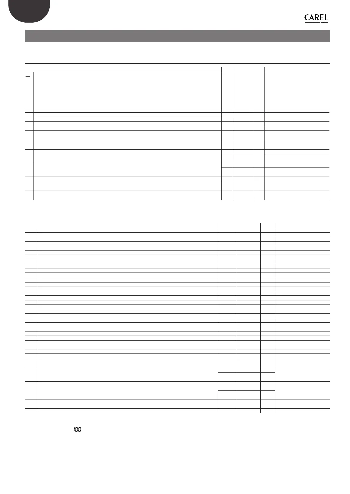
(*)
after 999 the display shows to indicate the 1000s (the three digits are displayed with a dot at the top between the rst and second digit).
Setting the value of parameter b0 in the range from 0 to 255 (default 7) changes the humidier operating options as regards the following preferences:
1. Unit of measure of parameter b1 (time between two periodical washing cycles): M = minutes; H = hours;
2. Backup: ON = if two humiSonic units, the secondary unit becomes the backup unit for the main unit, i.e. it starts production only if the main unit has shut down due to an
alarm; OFF = backup function disabled;
3. Position of the drain solenoid valve in standby: OPEN = standby empty, the NO valve is not powered and the humidier tank is emptied; CLOSED = standby full, the NO
valve remains powered, keeping the humidier tank full during standby;