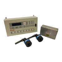
Figure 135 Link at Detector Connections
If the buzzer sounds at the Control Panel while the link is in place, replace the detector cable.
If the buzzer does not sound at the Control Panel while the link is in place, replace the Junction
Box PCB.
6. Reset the Control Panel.
7. Perform a Backup Alarm Test via the Test Menu, see Error! Reference source not found., to ensure
that the fault has been cleared.
Warning: The Common Alarm Relay may be activated during the diagnostic testing.
5.2.1.2 All detectors on an engine in fault
Having established which engine is in fault it is necessary to establish the cause of the fault using the
following steps.
1. Using a wire link at the Control Panel connect the relevant backup alarm terminal to the 0v terminal.
If the buzzer sounds at the Control Panel while the link is in place, go to item 2.
If the buzzer does not sound at the Control Panel while the link is in place, replace the Control
Panel Interface Board.
2. Using a wire link at the Junction Box connect the backup alarm connection from the Control Panel,
TB9, to the 0v terminal.
Figure 136 Link on Junction Box TB9
If the buzzer sounds at the Control Panel while the link is in place, replace the Junction Box PCB.
If the buzzer does not sound at the Control Panel while the link is in place, replace the cable
between the Control Panel and Junction Box.

 Loading...